Performance Report SiT9120, 75MHz
Rev. 1.0; Date: May 07, 2012
This report contains sample performance data for SiT9120 - 75MHz with LVPECL output.
Conditions:
- Frequency 75 MHz
- Vdd 2.5V, 3.3V
- Room temperature
- Termination: o 50Ω to Vdd – 2V
Equipment:
| Equipment | Measurement / Purpose |
|---|---|
| Agilent DSA90604A (6GHz, 20Gsps) | Period jitter, Differential voltage swing, Rise/fall time |
| Agilent 5052B Signal Source Analyzer | Phase noise, integrated phase jitter |
| Agilent 34980A | Power supply current |
| Agilent E3631A, Agilent E3648A | Power supplies |
Test setup:
The test setup for measuring period jitter and waveform parameters is shown in Figure 1. In this setup the devices VDD pin is connected to 2V and GND pin to 2V – Vnom, where Vnom is the nominal VDD for the device (2.5V or 3.3V). This allows terminating the outputs directly to the 50ohm-to-GND termination inside the scope with 50ohm coax cables.
Differential measurement with an oscilloscope:
For jitter measurements, both DUT outputs are connected to scope channels. Signals from inputs are subtracted inside the oscilloscope. All measurements are applied to the differential waveform.
Phase noise.
For phase noise measurements, differential signal is converted to single-ended using impedance matching transformer.
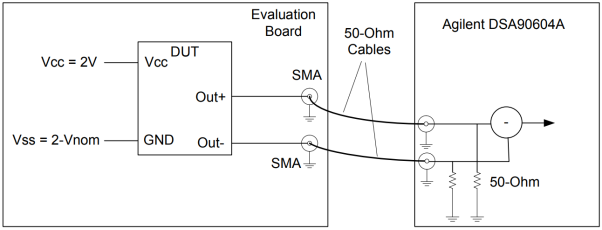
Figure 1.Test setup #1 for measuring period jitter, waveform parameters (rise/fall times, differential swing) and IDD
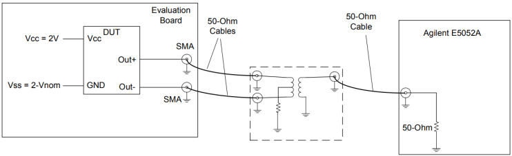
Figure 2. Test setup #2 for measuring phase noise.
Data:
- Random Phase jitter
- Period jitter
- Idd
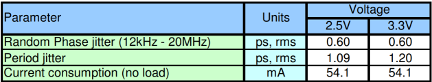
Table 1. Performance data
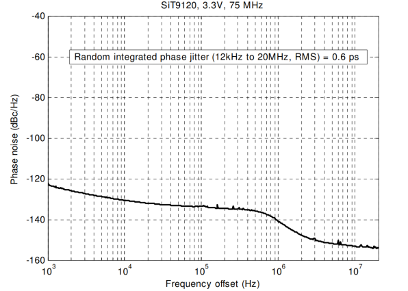
Figure 3. Phase noise plot 3.3V
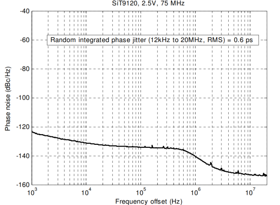
Figure 4. Phase noise plot 2.5V
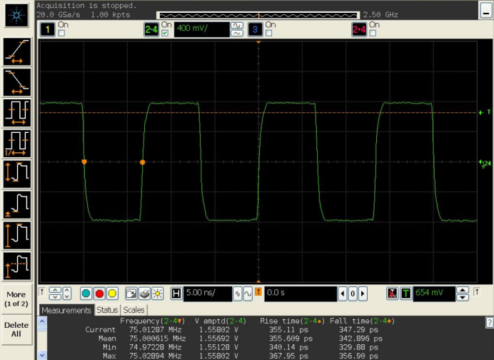
Figure 5. Waveform 3.3V
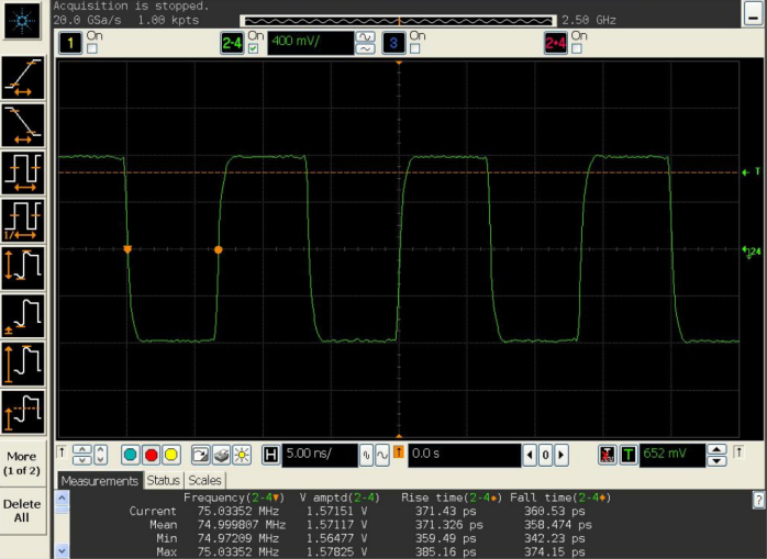
Figure 6. Waveform 2.5V