Electronic Detonators for Mining

Foreground: Detonator box of yellow color intended for detonating explosives; Background: Mining blast at an open pit copper mine

The timing accuracy of mining detonators has a significant influence on the safety and effectiveness of blasting operations. The detonation train needs precise timing. A lack of precise control can result in undesirable outcomes.

Detonators must be resilient and reliable. They must be designed to avoid misfires under the harshest of conditions such as shock from nearby explosions, ground vibration, gas or water intrusion, temperature extremes, and EMI. SiTime MEMS timing solutions are designed to operate under such extreme conditions and provide the required robustness and reliability for safe operation.

Download Application Brief

SiTime MEMS Timing Benefits

Complete MEMS clock tree

Small-footprint oscillators (XO)

Low jitter differential XO

Low power 32.768 XO

Accurate and robust

Resilience to shock, vibration, EMI

Hermeticity of the MEMS resonators

Excellent stability over temperature

Easy to use, built to last

Programmable features

No quartz reliability issues

>2 billion hour MTBF

Detonators (also called blasting caps) are used to trigger an explosive device in applications such as mining, quarrying and civil engineering. Commercial explosives are made stable and safe to handle, so they will not explode if accidentally dropped, mishandled or exposed to fire. For this reason, they require a small initiating explosion to be set off. This is provided by a detonator.

The timing accuracy of detonators used in the mining industry has a significant influence on the safety and effectiveness of blasting operations. A "detonation train" with precise timing is used to blast rock; lack of precise control can result in undesirable outcomes such as flyrock (rocks projected by the blast in an undesired direction), excessive ground vibration, uneven grade of rock as well as misfires or unintended firing.

Wired Detonators Block Diagram

Individual wired detonators are usually connected in parallel, via a differential line, to a programming and firing unit. The line provides both power as well as individual commands – such as delay programming, arming, disarming and firing – to the detonators. The firing order is programmed into the detonators by adjusting a time delay from the start of the sequence, to the moment the individual detonator fuses. All detonators are triggered simultaneously; the individual delay of each detonator executes the blast pattern.

Resilience and reliability are key parameters for detonators. They must be designed to avoid misfires and unintended firing under the harshest of conditions: shock from nearby explosions, ground vibration, gas or water intrusion, temperature extremes, etc. EMI interference is a common reason for unintended firing, which can be caused by lightning, static electricity, nearby radiofrequency transmitters, or stray currents from defective equipment.


Image
Block Diagram – Wired Detonators


Once the firing sequence is initiated and explosions start, detonators are likely to be disconnected from the power + communication line. For this reason, they feature an internal power supply capacitor which keeps them running until the fuse is triggered. The timing until the fuse is fired is managed by a microcontroller, using a reliable timing source such as the SiT1811 oscillator.


Wireless Detonators Block Diagram

Wireless detonators follow a similar operating principle as wired detonators. They are battery-powered and replace the power + communication line by radio transmission. Several techniques exist to create wireless transmitters and receivers; some of them rely on a clock source. A high-stability, low-jitter clock source enables more reliable transmission, lower error rate, and less interference.


MEMS Timing for Electronic Detonators

Devices Key Features Key Values
MHz oscillator
SiT8021  1 to 26 MHz
Buy Now
  • -40°C to +85°C
  • ±50 ppm stability
  • 1.5 x 0.8 CSP package
  • High reliability
  • EMI resilience
  • Low power
  • Small footprint
  • Excellent frequency stability
  • MEMS reliability
32.768 kHz oscillator
  • ±20, ±50 ppm stability
  • 1.14 to 3.3 V supply
  • 490 nA typ. current consumption (no load)
  • Up to -40°C to +105°C
  • 1.2 x 1.1 mm QFN
  • High reliability
  • EMI resilience
  • Low power
  • Small footprint
  • Excellent frequency stability
  • MEMS reliability
Differential oscillator
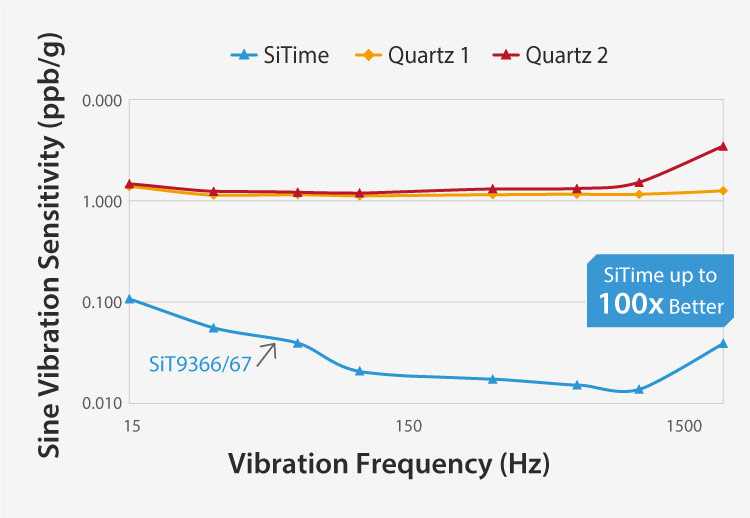
SiT9366  1 to 220 MHz
Buy Now
SiT9367  220 to 725 MHz
Buy Now
  • Low jitter 0.23 ps RMS [1]
  • LVPECL, LVDS, HCSL
  • 2.5 to 3.3 V
  • -40°C to 105°C
  • 3.2 x 2.5 mm package
  • Meets demanding jitter requirements
  • Small PCB footprint, easier layout
  • Easy design due to flexibility
  • MEMS reliability

1 12 kHz to 20 MHz integration range

SiTime Timing Solutions Advantages

  • Resilience to shock and vibration ensures the detonators keeps working despite nearby explosions.
  • EMI Resilience minimizes the risk of wrong timing, misfiring or unintended firing.
  • Frequency accuracy and stability over temperature range ensures perfect blast timing regardless of operating conditions.
  • Low Power maximizes the operating time on the power supply capacitor or battery; alternatively, it enables using a smaller, lower cost capacitor or battery.
  • Hermeticity of the MEMS resonators ensures the timing component is and not subject to performance degradation or failure in the presence of external contaminants.
  • Small form factor enables building smaller detonators.
  • Programmable, low jitter differential oscillators are a perfect clock source for wireless receivers.

MEMS Timing Outperforms Quartz

Higher Reliability

Better Quality, More Robust

Image
SiTime timing devices are up to 50x more reliable than legacy quartz
Image
SiTime – Better Quality, More Robust


Millions of Configurations

Immune to Vibration

Image
SiTime – Millions of Configurations
Image
SiTime – Immune to Vibration
contact support 2

Need samples or more information?

Contact Us Request Samples