Phase Noise Spreadsheet Calculator | Back to Development Calculators
About this Calculator
Many industry standards specify jitter generation compliance with a maximum phase jitter value in units of rms ps. One method to determine compliance is to measure phase-noise data and use it to calculate phase jitter. However, it is sometimes confusing how to do this conversion. An additional complication arises if the industry standard specifies jitter compliance numbers after a specific high-pass or band-pass filter has been applied. The below spreadsheet calculator performs these operations, and reveals the math behind them.
The spreadsheet calculator assumes that phase noise has been measured and its raw data is available in columnar form as (frequency, dBc/Hz), for example. The calculator also assumes the raw data is a long list of (x,y) data for (Hz, dBc/Hz), and represents an accurate piecewise linear approximation of the actual data plotted on a linear-linear scale.
Download the Phase Noise Spreadsheet Calculator
How the spreadsheet integrates phase noise
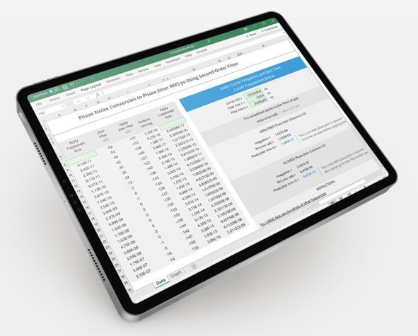
Download, then open the Excel file, and review the first two columns of example data (files were saved to support Excel 97 and later versions). The example data uses an arbitrary 2nd order filter that can be customized.
The calculator begins by taking the anti-log of the dBc/Hz data to assist integration. To keep things simple, the trapezoidal rule is applied to integrate between data points. More accurate integration methods are possible, but the end result will not change assuming your instrument's frequency step size is sufficiently small (try to use at least 20 data-points per decade, to make sure the sampled data is a piece-wise linear approximation of the actual phase-noise curve). For simplicity, the spreadsheet downloaded here represents only a limited data set. Your actual data file should contain much more data.
The calculator completes the integration by summing the data in the trapezoidal rule column. Since the phase-noise measurement only accounts for a single-sideband, multiply this number by two to capture the other sideband. The resulting number is the variance. Take its square root to obtain the standard deviation of phase jitter in radians. Because the distribution's mean is zero, this is more commonly refered to as rms phase jitter in practice. Divide by 2*pi*fc to convert the rms phase jitter unit from radians to seconds, where fc is the carrier frequency. Click on the Graph tab in the Excel file to view the example phase noise graphs.
The calculator also enables filtering for jitter as required by various industry standards. Notice the industry-standard specified parameters (carrier and pole frequencies) located on the spreadsheet's right-hand side. Different standards may be accommodated by changing these values as defined by a particular standard. Standards requiring jitter filters for jitter generation measurements will specify high-pass or pass-band jitter filters and provide these zero and pole frequencies, as well as roll-off characteristics. From this information a transfer function of the filter can be modeled as a simple first or second order LaPlace function. Using simple math, the absolute magnitude of this function times its complex conjugate is the transfer function of this filter. The spreadsheet's Jitter Filter column expresses this value in dB. The jitter filter is easily applied to the raw data by adding their respective columns in dB. The calculator then integrates the filtered phase-noise data, first take its anti-log before applying the trapezoidal rule as done above. The conversion process is finished similarly as above.
Filtering Jitter
The calculator also enables filtering for jitter as required by various industry standards. Notice the industry-standard specified parameters (carrier and pole frequencies) located on the spreadsheet's right-hand side, as shown in the image below.
Different standards may be accommodated by changing these values as defined by a particular standard. Standards requiring jitter filters for jitter generation measurements will specify high-pass or pass-band jitter filters and provide these zero and pole frequencies, as well as roll-off characteristics. From this information a transfer function of the filter can be modeled as a simple first or second order LaPlace function. Using simple math, the absolute magnitude of this function times its complex conjugate is the transfer function of this filter. The spreadsheet's Jitter Filter column expresses this value in dB. The jitter filter is easily applied to the raw data by adding their respective columns in dB. The calculator then integrates the filtered phase-noise data, first take its anti-log before applying the trapezoidal rule as done above. The conversion process is finished similarly as above.

