Industrial Cameras

Robotic vision sensor camera system in intellegence factory

Industrial cameras are a key element of machine vision systems. Camera systems are based on a CMOS imager, an SoC or FPGA, and various interfaces to transfer images. Each of these functions require a robust timing device – one that can reliably operate at the required frequency and in harsh industrial environments. SiTime MEMS-based timing solutions offer the breath of frequencies and features needed along with the robustness to survive a range of dynamic conditions.

Download Application Brief

SiTime MEMS Timing Benefits

Complete MEMS clock tree

Small-footprint oscillators (XO)

Low jitter differential XO

Low power 32.768 XO

Most robust in real world conditions

Excellent stability over temperature

Better shock/vibration resistance

Higher quality and reliability

Easy to use, built to last

Custom configured solutions

No quartz reliability issues

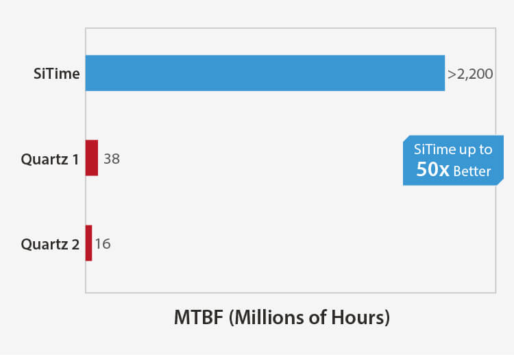
>2 billion hour MTBF

Industrial cameras are a key element of machine vision systems. Typical applications include automatic imaging-based inspection, process control, robot guidance, surveillance, microscopy, motion analysis, mapping, document digitizing, as well as medical imaging. Data collected by cameras are usually processed by a computer, with or without artificial intelligence.

Camera systems are based on a CMOS imager, a processing SoC or FPGA, and interfaces to transfer images to the "outside world." Depending on the application, imagers of different resolutions and frame rates are chosen. CMOS image sensors exist in different sizes. In general, the larger the sensor size, the better the dynamic range and signal-to-noise (SNR) ratio.

An SoC or FPGA processes the data collected by the image sensor. Typical processing includes creating usable still images or a video stream from the raw sensor data and compressing them for transmission. More advanced processing such as pattern recognition can be performed either in-camera, or in a central computer.

Various interfaces to connect cameras to other elements of a machine vision system exist. The most common are Ethernet, USB, GMSL (Analog Devices), V3-Link and FPD-Link (Texas Instruments). Wi-Fi or proprietary wireless interfaces can also be used.

Industrial Cameras Block Diagram

Typical CMOS imagers require a fixed frequency clock between 6 MHz and 72 MHz. As a general rule, the higher the sensor data rate, the higher the clock frequency. The data rate mainly depends on three characteristics:

  • resolution, related to sensor size (ranging from 5 x 4 mm to 54 x 40 mm) and pixel pitch
  • frames per second
  • bits per pixel

As digital devices, SoCs and FPGAs can be easily clocked with a single-ended oscillator in the 10 to 40 MHz range such as the SiT1603. An optional 32.768 kHz oscillator can be added if real-time-clock timekeeping is needed. A low-power oscillator such as the SiT1811, consuming only 6 μA, enables accurate time keeping in standby mode.

Interface clocking depends on the chipset; in general:

  • Ethernet with a single-ended 25 MHz
  • USB with a single-ended 48 MHz or a differential 100 MHz
  • GMSL with a single-ended clock with frequency such as 25 MHz
  • V3-Link and FPD-Link with a single-ended frequency in the range of 25 MHz to 100 MHz

MEMS Timing Solutions for Industrial Cameras

Devices Key Features Key Values
MHz oscillator
SiT8008  1 to 110 MHz
Buy Now
SiT1602  52 std freqs from 3.57 to 77.76 MHz
Buy Now
  • -40°C to +85°C
  • ±20 ppm stability
  • 5 std package sizes
  • High reliability
  • Flexible frequency options
  • Excellent stability over temperature
MHz oscillator
SiT8021  1 to 26 MHz
Buy Now
  • -40°C to +85°C
  • ±50 ppm stability
  • 1.5 x 0.8 CSP package
  • High reliability
  • Extended temperature range
  • Small footprint
  • Wide programmable freq range
MHz oscillator
SiT1603 [1]  8 to 76.8 MHz (various specific frequencies)
  • -40°C to +85°C
  • ±25 ppm stability
  • 2 mA current consumption
  • 0.75 fs rms phase jitter
  • High reliability
  • Low power
  • Various standard package options
Differential oscillator
SiT9366  1 to 220 MHz
Buy Now
  • Low jitter 0.23 ps RMS [1]
  • LVPECL, LVDS, HCSL
  • 2.5 to 3.3 V
  • -40°C to 105°C
  • 3.2 x 2.5 mm package
  • Meets demanding jitter requirements
  • Small PCB footprint, easier layout
  • Easy design due to flexibility
  • MEMS reliability
32.768 kHz oscillator
SiT1811 [1]  
  • ±20, ±50 ppm stability
  • 1.14 to 3.3 V supply
  • typ. 490 nA current consumption (no load)
  • Up to -40°C to +105°C
  • 1.2 x 1.1 mm QFN
  • Low power
  • Small footprint
  • Excellent stability enables better time keeping over longer periods of standby time, thus saving even more power
32.768 kHz oscillator
SiT1552  
Buy Now
  • ±5, ±10, ±20 ppm stability
  • 1 μA current consumption
  • Up to -40°C to +85°C
  • 1.5 x 0.8 CSP package
  • Low power
  • Small footprint
  • Excellent stability enables better time keeping over longer periods of standby time, thus saving even more power

1 Please contact SiTime for availability.

SiTime Advantages

  • Up to 2x better stability, 10x lower jitter than crystal-based oscillators
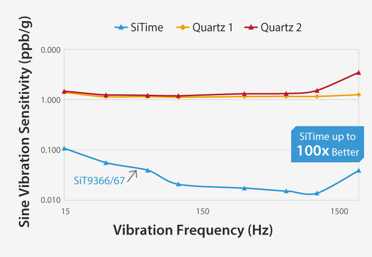
  • Up to 50x better immunity to EMI than crystal-based oscillators
  • EMI reduction features
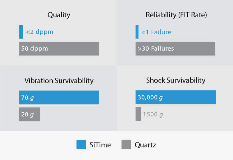
  • 30x better shock and vibration resistance
  • Factory programmable to any frequency
  • Wide operating temp (-40°C to 105°C)
  • Industry-leading small package sizes down to 1.5 x 0.8 mm CSP

MEMS Timing Outperforms Quartz

Higher Reliability

Better Quality, More Robust

Image
SiTime timing devices are up to 50x more reliable than legacy quartz
Image
SiTime – Better Quality, More Robust


Millions of Configurations

Immune to Vibration

Image
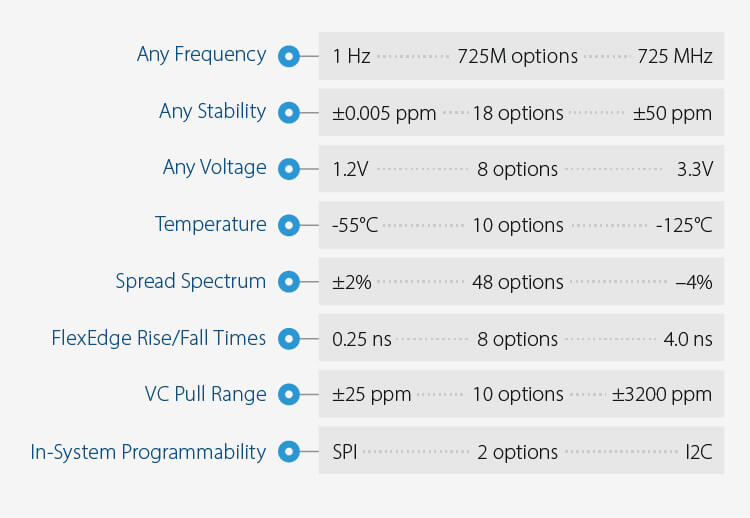
SiTime – Millions of Configurations
Image
SiTime – Immune to Vibration
contact support 2

Need samples or more information?

Contact Us Request Samples