Automotive LiDAR

Radar_and_Lidar_image_4

LiDAR, together with radar and camera vision, is one of the key sensing elements of ADAS systems. Precision timing and low jitter are critical in LiDAR systems. SiTime MEMS oscillators provide frequency stability over temperature with AEC-Q100 grade 1 (-40°C to +125°C) reliability. Our differential oscillators provide ultra-low jitter, enabling the reliable and rapid transfer of data. Compared to quartz oscillators, SiTime timing solutions offer higher reliability, better resilience to shock, vibration and EMI, and faster startup.

Download Application Brief

SiTime MEMS Timing Benefits

Complete MEMS clock tree

Spread spectrum oscillators

Low jitter differential oscillators

32.768-kHz XOs and TCXOs

Precision TCXOs

Most robust in real world conditions

150 fs rms jitter, excellent PSNR

Resistant to shock and vibration

Stable over wide temperature

>2 billion hours MTBF

Integrated MEMS, easy to use

No quartz reliability issues

Reliable startup in cold temp

No cover or shielding needed

Short lead time for any frequency

LiDAR Block Diagram

LiDAR (light detection and ranging) determines range by targeting an object with laser and measuring the time for the reflected light to return to the receiver. LiDAR systems scan the vision field vertically and horizontally, some can scan 360°, hence creating a 3D representation of the environment around a vehicle.

At the core of a LiDAR system are a solid-state laser source, a detector and the analog front end (AFE). An ADC samples the signal received by the AFE. After processing, the data collected by the LiDAR system is sent to a domain controller or ADAS computer via a PHY. Many different interfaces exist, for instance Ethernet, FPD-Link (TI) or GMSL (Analog Devices). Open standards such as Automotive Serdes Alliance (ASA) or MIPI A-PHY are emerging. Depending on the interface, either a single ended or a differential clock will be needed.

MEMS Timing Solutions for LiDAR

Devices Key Features Key Values
Single-ended Oscillator
SiT8924  1 to 110 MHz
Buy Now
  • Up to -55°C to +125°C
  • ±20 ppm stability
  • 2016, 2520, 3225 packages
  • High reliability
  • Extended temperature range
  • Small footprint
Single-ended Oscillator
SiT9025  1 to 110 MHz
Buy Now
  • Up to -55°C to +125°C
  • Spread spectrum
  • Configurable rise / fall times
  • 2016, 2520, 3225 packages
  • High reliability
  • Extended temperature range
  • EMI Reduction
Differential Oscillators
SiT9396  1 to 220 MHz
Buy Now
SiT9397  220 to 920 MHz
Buy Now
  • Low jitter: < 150 fs RMS [1]
  • ±30, ±50 ppm stability over -40 to +125°C
  • LVPECL, LVDS, HCSL, Low-power HCSL, FlexSwing™
  • 2016, 2520, 3225 packages
  • High reliability
  • Low jitter
  • Enables interfaces with demanding jitter requirements, such as PCI-Express and 10 GB Ethernet
Super-TCXOs
SiT5386  1 to 60 MHz
Buy Now
SiT5387  60 to 220 MHz
Buy Now
  • ±0.1, ±0.2, ±0.25 ppm stability over -40 to +125°C
  • ±1 ppb/°C frequency slope
  • Low jitter: 0.31 ps RMS [1]
  • Optional voltage or digital frequency control
  • High accuracy
  • Excellent frequency stability with fast temp gradients
  • No GNSS signal loss or V2X disconnect due to micro-jumps

1 12 kHz to 20 MHz integration range

Automotive LiDAR

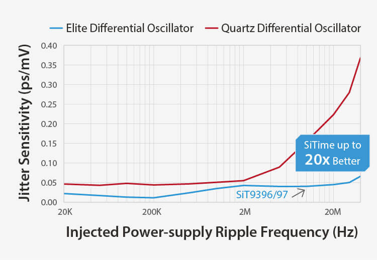
Several measurement methods exist: Time of flight (ToF), frequency modulated continuous wave, or time digital conversion (TDC). Precision timing plays a big role to ensure accuracy of the system. The low jitter of the SiT9396 and SiT9397 make those devices ideal to clock the analog part of LiDAR applications.

Image
Automotive LiDAR Jitter

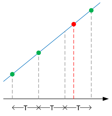
When an ADC is used, jitter causes quantization errors. When excessive jitter is present on a clock, in other words when a clock edge comes too early or too late, an ADC samples the incoming signal at the wrong moment. Incorrect values in the data stream can significantly hamper the functionality of a system.

The excellent dynamic performance of SiTime silicon MEMS oscillators facilitate SOTIF (safety of the intended functionality) compliance of the system. The MEMS oscillators ensure that clocks remain within spec over its entire lifetime, regardless of environmental changes.

  • Temperature range -40°C to +125°C
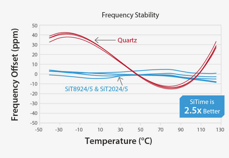
  • Well controlled frequency stability: < ±30 ppm over the full temperature range, including 10 years aging (SiT939x), down to ±0.1 ppm for TCXO (SiT538x)
  • Excellent frequency response to rapid temperature changes dF /dT, down to < ±3.5 ppb/°C (SiT538x)


SiTime Advantages

All SiTime devices offer the following advantages over quartz crystals, which are particularly important for automotive applications:

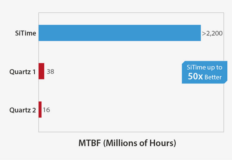
  • 50x better reliability. Apart from reducing the amount of field failures, the better reliability translates into a lower FIT rate. This provides better hardware safety metrics in an FMEDA, the quantitative analysis required as part of a functional safety assessment.
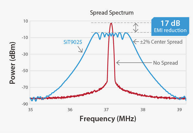
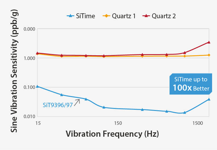
  • 100x better resilience to shock, vibration and electromagnetic interference, due to the smaller size (0.4 x 0.4 mm) and lower mass of MEMS resonators compared to crystals.
  • MEMS oscillators typically have a faster startup time than crystal oscillators.

MEMS Timing Outperforms Quartz

Higher Quality

Higher Reliability

Image
 SiTime – Higher Quality
Image
SiTime timing devices are up to 50x more reliable than legacy quartz


Tighter Stability

Better EMI Reduction

Image
SiTime – Tighter Stability
Image
SiTime – Better EMI Reduction


Immune to Vibration

Better Noise Rejection

Image
SiTime – Immune to Vibration
Image
SiTime – Better Noise Rejection
contact support 2

How can we help you?

Contact Us Request Samples