Manufacturing Notes for SiTime MEMS-Based Silicon Timing Products
1. Introduction
These manufacturing notes apply to all SiTime MEMS-based silicon timing products in quad flat no-lead (QFN), SOT23-5, 2.0 x 1.2 mm SMD, WLCSP, ceramic, and stacked-PCB packages. The information in this document is provided to assist customers with manufacturing set-up and use of SiTime products designed into systems.
The materials used in the construction of SiTime products comply with Green standards. They are compliant to current RoHS and REACH SVHC requirements. Material composition reports are available on the SiTime website and can be made available upon request from your sales representative. SiTime products meet all governmental hazardous material regulations. MSDS reports are available upon request for the homogeneous materials used to make SiTime products but are not required for finished SiTime products.
All SiTime products have been qualified to JEDEC JESD47, AEC-Q100, or MIL STD 883 requirements, as applicable to the product and package. Reliability reports are available on the SiTime website or upon request from your sales representative.
2. Device Packaging
Detailed mechanical dimensions for the various body sizes are provided in the datasheets as package outline drawings.
2.1 Package Marking Details – Standard Mark
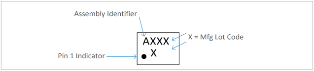
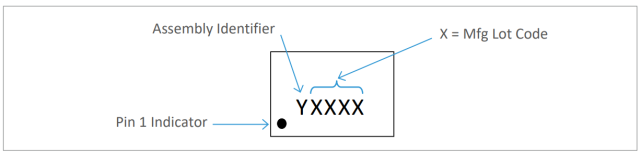
The standard mark for all SiTime products is shown below. It contains an assembly location code and lot code to allow tracing the manufacturing origin. This marking is used on all samples, low volume and mass production orders. The marking method is laser mark.
2.0 x 1.6 mm package marking diagram
Other packages marking diagram
In the above diagrams, which show the “STANDARD MARK”:
“Y” denotes assembly identifier:
- A or Z as a first letter to indicate Vendor Carsem
- B or Y as a first letter to indicate Vendor UTAC
- C or X as a first letter to indicate Vendor ASE
- E or V as a first letter to indicate Vendor KDS G or T as a first letter to indicate Vendor HANA X, Y, Z, V, T character used for marking of Conditional Released parts where full qualification is not completed.
“XXXX” denotes four alpha-numeric characters of the manufacturing lot code without any dashes, periods, or symbols.
For QFN 2.0 x 1.2, following are the marking requirements to identify the assembly sites.
- Line 1 : Last 4 digits of Lot code ( 4 characters max)
- Line 2 : Assembly location (Underline) – depending on assembly location.
- Underline under 2nd digit to indicate Vendor Carsem - Underline under 3rd digit to indicate Vendor UTAC
- Underline under 4th digit to indicate Vendor HANA
Top Marking Dimensions (otherwise indicated differently)
- All dimensions are in mm
- Font type: LLGOTHIC_ STD or EO135P or EO145
- Tolerance for:
- Dimensions X, X1, Y and Y1: ±0.25 mm
- Dimension Y2: ±0.1 mm
- Char Pitch: ±0.1 mm
- Char Height/Width: ±0.1 mm
- Pin 1 Dot Diameter: ±0.1 mm
- All other tolerances: ±0.20 mm
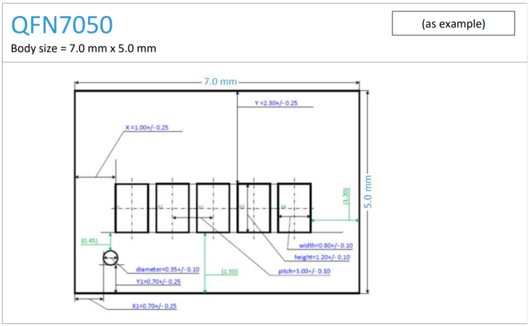
Figure 1: Standard Marking Dimensions – 5.0 x 2.0, 3.2 x 2.5, 5.0 x 3.2, 7.0 x 5.0 mm, and SOT23 Packages
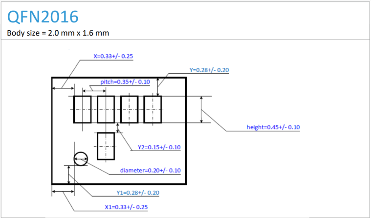
Figure 2: Standard Marking Dimensions for 2.0 x 1.6 mm Package
Table 1: Marking Dimensions for Package Type
| Package | X | X1 | Y | Y1 | Y2 | Char Height |
Char Width |
Char Pitch |
Pin 1 Dot Diameter |
|---|---|---|---|---|---|---|---|---|---|
| 2.5 x 2.0 | 0.30 | 0.30 | 0.85 | 0.25 | N/A | 0.45 | N/A | 0.35 | 0.25 |
| SOT23 | 0.55 | 0.30 | 0.81 | 0.25 | N/A | 0.40 | N/A | 0.35 | 0.16 |
| 2.7 x 2.4 | 0.30 | 0.30 | 0.85 | 0.25 | N/A | 0.45 | N/A | 0.35 | 0.25 |
| 3.5 x 3.0 | 0.30 | 0.30 | 1.10 | 0.35 | N/A | 0.45 | N/A | 0.45 | 0.25 |
| 3.2 x 2.5 | 0.30 | 0.20 | 1.10 | 0.35 | N/A | 0.45 | N/A | 0.45 | 0.25 |
| 5.0 x 3.2 | 0.80 | 0.35 | 1.80 | 0.5 | N/A | 0.90 | 0.60 | 0.80 | 0.25 |
| 7.0 x 5.0 | 1.00 | 0.70 | 2.30 | 0.7 | N/A | 1.20 | 0.80 | 1.00 | 0.35 |
| 2.0 x 1.6 | 0.33 | 0.33 | 0.28 | 0.28 | N/A | 0.45 | N/A | 0.35 | 0.20 |
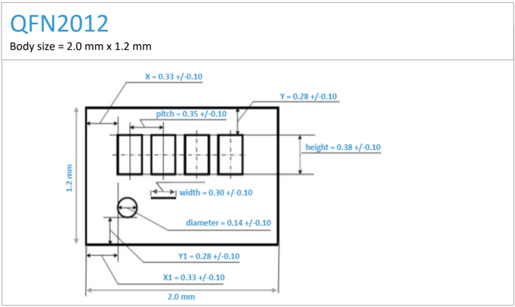
Figure 3: Standard Marking Dimensions for 2.0 mm x 1.2 mm Package
Table 2: Marking Dimensions for SMD Package Type (2.0 mm x 1.2 mm)
| Package | Char Height |
Underline Width |
Char Pitch |
Pin 1 Diameter |
X | Y | Y1 |
|---|---|---|---|---|---|---|---|
| 2.0 x 1.2 | 0.38 | 0.3 | 0.35 | 0.14 | 0.33 | 0.28 | 0.28 |
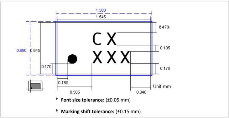
Figure 4: Standard Marking Dimensions for WLCSP Package (1.5 mm x 0.8 mm)
Table 3: Marking Dimensions for WLCSP Package (1.5 mm x 0.8 mm)
| Item | Description | Position | Font Type | Height ▯ ↕ |
Width ▯ ↔ |
Space ▯ ↔▯ |
Max Marking Width ▯▯▯▯▯ ←――→ |
Max chars |
|---|---|---|---|---|---|---|---|---|
| Pin 1 Dot | Dot | NA | NA | 0.15 mm | 0.15 mm | NA | NA | NA |
| Line 1 | CX | Left | S_X.FNT | 0.20 mm | 0.18 mm | 0.05 mm | 0.41 mm | 2 |
| Line 2 | XXX | Left | S_X.FNT | 0.20 mm | 0.18 mm | 0.05 mm | 0.64 mm | 3 |
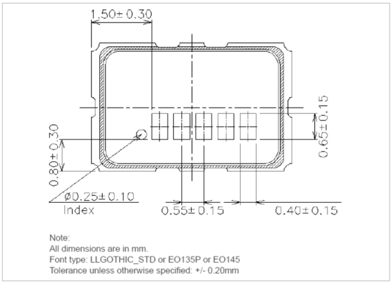
Figure 5: Standard Marking Dimensions for Ceramic Package (5.0 mm x 3.2 mm)
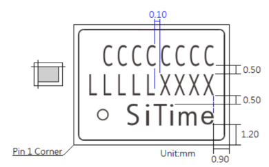
Figure 6: Marking Dimensions for Emerald and Epoch Package (9.0 mm x 7.0 mm)
Table 4: Marking Dimensions for Emerald and Epoch Package (9.0 mm x 7.0 mm)
| Item | Description | Position | Font Type | Height ▯ ↕ |
Width ▯ ↔ |
Space ▯ ↔▯ |
Max Marking Width ▯▯▯▯▯ ←――→ |
Max chars |
|---|---|---|---|---|---|---|---|---|
| Logo | SiTime | NA | NA | 1.20 mm | 5.20 mm | NA | NA | NA |
| Line 1 | CCCCCCCC | Right | EO145.FNT | 1.20 mm | 0.70 mm | 0.10 mm | 7.10 mm | 9 |
| Line 2 | LLLLL | Right | EO145.FNT | 1.20 mm | 0.70 mm | 0.10 mm | 3.90 mm | 5 |
| Line 2 | XXXX | Right | EO145.FNT | 1.20 mm | 0.70 mm | 0.10 mm | 3.10 mm | 4 |
Where,
Tolerance: Font size: =/- 0.10 mm; Marking Shift: =/- 0.25 mm
Line 1: CCCCCCCC – this is frequency mark request (empty if not required)
Line 2: LLLLL – 5-digit lot code marking
Line 2: XXXX – part serial number from production panel
Line 3: Pin 1 dot and “SiTime” logo
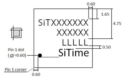
Figure 7: Marking Dimensions for Cascade Package (QFN 9.0 mm x 9.0 mm)
Note: Line 1 and 2 marking will be done post testing and line 3 and logo1 marking will be done during assembly builds.
Table 5: ASSY Marking
| Item | Description | Position | Font Type | Height ▯ ↕ |
Width ▯ ↔ |
Space ▯ ↔▯ |
Max Marking Width ▯▯▯▯▯ ←――→ |
Max chars |
Char Limit |
|---|---|---|---|---|---|---|---|---|---|
| Logo1 | SiTime | Right | NA | 1.05 mm | 4.55 mm | NA | NA | NA | Logo name - SiTime |
| Line 3 | LLLLL | Right | EO145.FNT | 1.05 mm | 0.60 mm | 0.20 mm | 3.80 mm | 9 | A |
Table 6: FT Post Marking
| Item | Description | Position | Font Type | Height ▯ ↕ |
Width ▯ ↔ |
Space ▯ ↔▯ |
Max Marking Width ▯▯▯▯▯ ←――→ |
Max chars |
Char Limit |
|---|---|---|---|---|---|---|---|---|---|
| Line 1 | SiTXXXXXXX | Right | EO145.FNT | 1.05 mm | 0.60 mm | 0.20 mm | 3.80 mm | 10 | A |
| Line 2 | XXXXXXX | Right | EO145.FNT | 1.05 mm | 0.60 mm | 0.20 mm | 3.80 mm | 6 | A |
Where,
Tolerance: ±0.20 mm
Line 1: “SiTXXXXXXX”, 1st to 10th characters of part number
Line 2: “XXXXXX”, 11th to 16th characters of part number, excluding tape and reel suffix
Line 3: “LLLLL”, 5 digits lot code marking
Line 4: Pin 1 dot and “SiTime” logo
All dimensions are in mm.
Font type: LLGOTHIC_STD or EO135P or EO145
Font Size Tolerance unless otherwise specified: ±0.10mm
Top (1) Marking shift tolerance: (±0.25 mm)
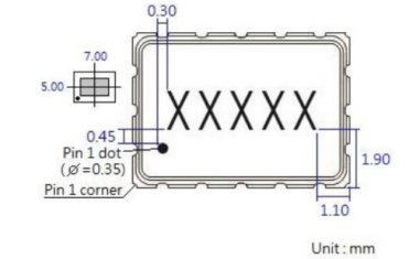
Figure 8: Standard Marking Dimensions for Ceramic Package (7.0 mm x 5.0 mm)
Table 7: Marking Dimensions for Ceramic Package (7.0 mm x 5.0 mm)
| Top (1) Item | Description | Position | Font Type | Height ▯ ↕ |
Width ▯ ↔ |
Space ▯ ↔▯ |
Max Marking Width ▯▯▯▯▯ ←――→ |
Max chars |
Chars Limit |
|---|---|---|---|---|---|---|---|---|---|
| Line 1 | XXXXX | Center | EO145.FNT | 1.20 mm | 0.80 mm | 0.20 mm | 4.80 mm | 5 | B |
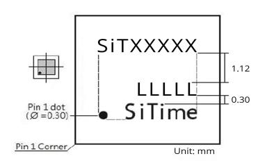
Figure 9: Marking Dimensions for QFN 5.0 mm x 5.0 mm Package
Note: Line 1 and 2 marking will be done post testing and line 3 and logo1 marking will be done during assembly builds.
Table 8: ASSY Marking
| Top (1) Item | Description | Position | Font Type | Height ▯ ↕ |
Width ▯ ↔ |
Space ▯ ↔▯ |
Max Marking Width ▯▯▯▯▯ ←――→ |
Max chars |
Logo Name |
|---|---|---|---|---|---|---|---|---|---|
| Logo 1 | SiTime | Center | NA | 0.60 mm | 2.46 mm | NA | NA | NA | SiTime |
| Top (1) Item | Description | Position | Font Type | Height ▯ ↕ |
Width ▯ ↔ |
Space ▯ ↔▯ |
Max Marking Width ▯▯▯▯▯ ←――→ |
Max chars |
Chars Limit |
|---|---|---|---|---|---|---|---|---|---|
| Line 1 | SiTXXXXX | Right | EO145.FNT | 0.52 mm | 0.30 mm | 0.15 mm | 3.45 mm | 8 | C |
| Line 3 | LLLLL | Right | EO145.FNT | 0.52 mm | 0.30 mm | 0.15 mm | 3.45 mm | 8 | A |
Where,
Tolerance: ±0.10 mm
Line 1: “SiTXXXXX”, 1st to 8th characters of part number
Line 2: Blank
Line 3: “LLLLL”, 5 digits lot code marking
Line 4: Pin 1 dot and “SiTime” logo
All dimensions are in mm.
Font type: LLGOTHIC_STD or EO135P or EO145
Font Size Tolerance unless otherwise specified: ±0.10mm
Top (1) Marking shift tolerance: (±0.25 mm)
3. Product Packing
3.1 Tape & Reel
The carrier tape basic dimensions are based on EIA481. The pocket is designed to hold the part for shipping and loading onto SMT manufacturing equipment, while protecting the body and the solder terminals from damaging stresses. The individual pocket design can vary from vendor to vendor, but width and pitch will be consistent.
Carrier tape is wound or placed onto a 7” or 13” shipping reel depending on the quantity of parts on the reel and the package body size.
The center hub design is large enough to ensure the radius formed by the carrier tape around it does not put unnecessary stress on the parts.
Prior to shipping, parts are placed into the pockets of the carrier tape. Moisture sensitive parts (MSL level 2a-5a) are baked prior to placement into the pockets of the carrier tape (refer to Sections 4, 6, and 7 for the baking/storage conditions). A cover tape is sealed over the top of the entire length of the carrier tape.
The reel is sealed in a protective bag with a dry N2 backfill. The reel is made with high impact polystyrene and is anti-static material. It is possible that color of the reels may be different in two different shipments depending on drop shipment location. However, the specifications of the reel are identical. The carrier tape is made with polystyrene with carbon impregnation and is static dissipative material. The cover tape is made with polystyrene antistatic material.
Figure 10 provides relevant dimensions of the carrier tape of Tape & Reel for all packages/PODs in production. Figure 11 provides the dimensions of the reel of the Tape & Reel packing.
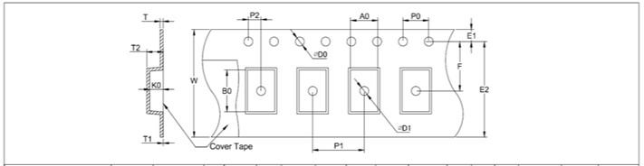
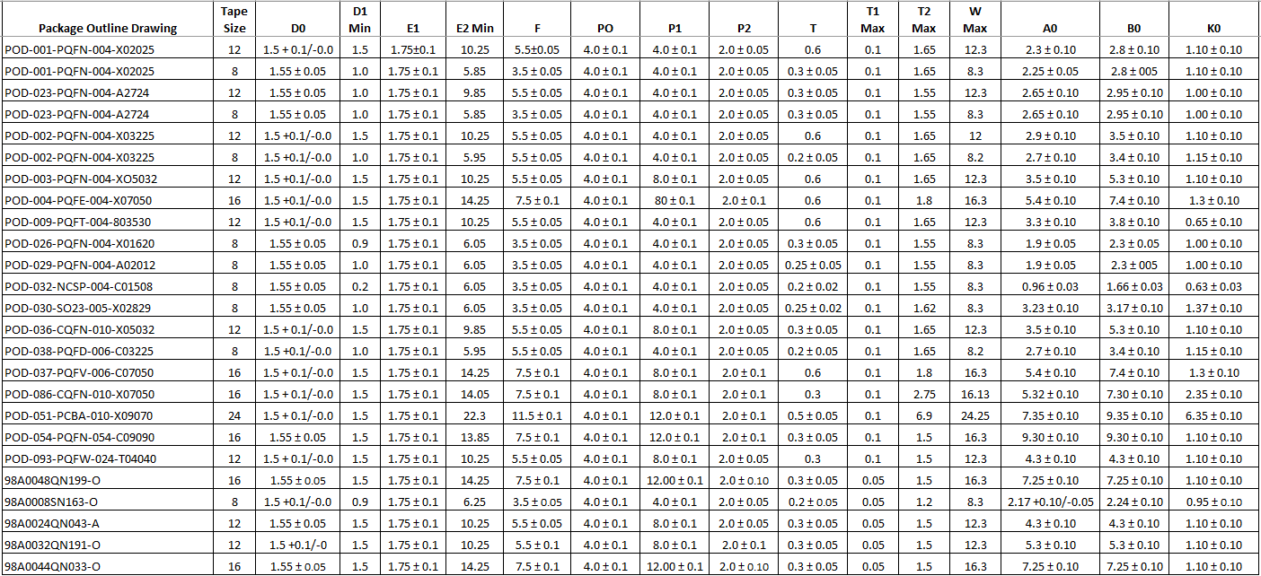
Note: All dimensions are in mm
Figure 10: Carrier Tape Dimensions
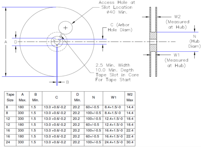
Figure 11: Reel Dimensions
Device orientation in the carrier tape is shown in the diagram below for all QFN, WLCSP, and module (SIP LGA) packages (Figure 12) and SOT23-5 package (Figure 13).
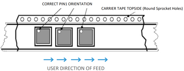
Figure 12: Standard Tape and Reel Pin 1 Orientation (Except for SOT-23)
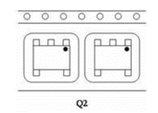
Figure 13: SOT23 Tape and Reel Pin 1 Orientation
Table 9 below provides the ordering details for tape and reel quantity, reel size, and top mark options. The “Suffix” character is the last character in the part number string as shown in the example below. Deviation from this table will be indicated via a custom part number (CS).
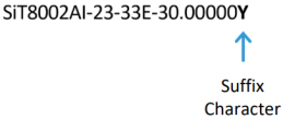
Table 9: Marking and Tape & Reel Option Selections with Part Number Coding
| Suffix | Packaging Method | Package Size (mm) | Reel Size (inches) | Qty per Reel | Top Mark |
|---|---|---|---|---|---|
| M | Bulk | All | N/A | Shipped in canister or ESD bag or tube – any qty |
2 Lines Frequency Mark |
| V | 16mm Tape & Reel | 7.0 x 5.0 | 13 | 3000 | 2 Lines Frequency Mark |
| V | 12mm Tape & Reel | 5.0 x 3.2 | 13 | 3000 | 2 Lines Frequency Mark |
| V | 12mm Tape & Reel | 3.2 x 2.5 | 7 | 3000 | 2 Lines Frequency Mark |
| V | 12mm Tape & Reel | 2.7 x 2.4 | 7 | 3000 | 2 Lines Frequency Mark |
| V | 12mm Tape & Reel | 2.5 x 2.0 | 7 | 3000 | 2 Lines Frequency Mark |
| Z | 16mm Tape & Reel | 7.0 x 5.0 | 7 | 1000 | 2 Lines Frequency Mark |
| Z | 12mm Tape & Reel | 5.0 x 3.2 | 7 | 1000 | 2 Lines Frequency Mark |
| Z | 12mm Tape & Reel | 3.2 x 2.5 | 7 | 1000 | 2 Lines Frequency Mark |
| Z | 12mm Tape & Reel | 2.7 x 2.4 | 7 | 1000 | 2 Lines Frequency Mark |
| Z | 12mm Tape & Reel | 2.5 x 2.0 | 7 | 1000 | 2 Lines Frequency Mark |
| W | 16mm Tape & Reel | 7.0 x 5.0 | 7 | 250 | 2 Lines Frequency Mark |
| W | 12mm Tape & Reel | 5.0 x 3.2 | 7 | 250 | 2 Lines Frequency Mark |
| W | 12mm Tape & Reel | 3.2 x 2.5 | 7 | 250 | 2 Lines Frequency Mark |
| W | 12mm Tape & Reel | 2.7 x 2.4 | 7 | 250 | 2 Lines Frequency Mark |
| W | 12mm Tape & Reel | 2.5 x 2.0 | 7 | 250 | 2 Lines Frequency Mark |
| H | 8mm Tape & Reel | 3.2 x 2.5 | 7 | 3000 | 2 Lines Frequency Mark |
| H | 8mm Tape & Reel | 2.5 x 2.0 | 7 | 3000 | 2 Lines Frequency Mark |
| H | 8mm Tape & Reel | SOT23 | 7 | 3000 | 2 Lines Frequency Mark |
| J | 8mm Tape & Reel | 3.2 x 2.5 | 7 | 1000 | 2 Lines Frequency Mark |
| J | 8mm Tape & Reel | 2.5 x 2.0 | 7 | 1000 | 2 Lines Frequency Mark |
| J | 8mm Tape & Reel | SOT23 | 7 | 1000 | 2 Lines Frequency Mark |
| K | 8mm Tape & Reel | 3.2 x 2.5 | 7 | 250 | 2 Lines Frequency Mark |
| K | 8mm Tape & Reel | 2.5 x 2.0 | 7 | 250 | 2 Lines Frequency Mark |
| K | 8mm Tape & Reel | SOT23 | 7 | 250 | 2 Lines Frequency Mark |
| T | 16mm Tape & Reel | 7.0 x 5.0 | 13 | 3000 | 1 Line Standard Mark |
| T | 16mm Tape & Reel | 9.0 x 9.0 | 13 | 3000 | 1 Line Standard Mark |
| T | 12mm Tape & Reel | 5.0 x 3.2 | 13 | 3000 | 1 Line Standard Mark |
| T | 12mm Tape & Reel | 3.2 x 2.5 | 7 | 3000 | 1 Line Standard Mark |
| T | 12mm Tape & Reel | 2.7 x 2.4 | 7 | 3000 | 1 Line Standard Mark |
| T | 12mm Tape & Reel | 2.5 x 2.0 | 7 | 3000 | 1 Line Standard Mark |
| Y | 16mm Tape & Reel | 7.0 x 5.0 | 7 | 1000 | 1 Line Standard Mark |
| Y | 16mm Tape & Reel | 9.0 x 9.0 | 7 | 1000 | 1 Line Standard Mark |
| Y | 12mm Tape & Reel | 5.0 x 3.2 | 7 | 1000 | 1 Line Standard Mark |
| Y | 12mm Tape & Reel | 3.2 x 2.5 | 7 | 1000 | 1 Line Standard Mark |
| Y | 12mm Tape & Reel | 2.7 x 2.4 | 7 | 1000 | 1 Line Standard Mark |
| Y | 12mm Tape & Reel | 2.5 x 2.0 | 7 | 1000 | 1 Line Standard Mark |
| N | 24mm Tape & Reel | 9.0 x 7.0 | 13 | 500 | 1 Line Standard Mark |
| X | 24mm Tape & Reel | 9.0 x 7.0 | 13 | 250 | 1 Line Standard Mark |
| X | 24mm Tape & Reel | 9.0 x 7.0 | 7 | 250 | 1 Line Standard Mark |
| X | 16mm Tape & Reel | 7.0 x 5.0 | 7 | 250 | 1 Line Standard Mark |
| X | 12mm Tape & Reel | 9.0 x 9.0 | 7 | 250 | 1 Line Standard Mark |
| X | 12mm Tape & Reel | 5.0 x 3.2 | 7 | 250 | 1 Line Standard Mark |
| X | 12mm Tape & Reel | 3.2 x 2.5 | 7 | 250 | 1 Line Standard Mark |
| X | 12mm Tape & Reel | 2.7 x 2.4 | 7 | 250 | 1 Line Standard Mark |
| X | 12mm Tape & Reel | 2.5 x 2.0 | 7 | 250 | 1 Line Standard Mark |
| D | 8mm Tape & Reel | 3.2 x 2.5 | 7 | 3000 | 1 Line Standard Mark |
| D | 8mm Tape & Reel | 2.5 x 2.0 | 7 | 3000 | 1 Line Standard Mark |
| D | 8mm Tape & Reel | 2.0 x 1.6 | 7 | 3000 | 1 Line Standard Mark |
| D | 8mm Tape & Reel | 2.0 x 1.2 | 7 | 3000 | 1 Line Standard Mark |
| D | 8mm Tape & Reel | SOT23 | 7 | 3000 | 1 Line Standard Mark |
| D | 8mm Tape & Reel | 1.5 x 0.8 | 7 | 3000 | 1 Line Standard Mark |
| C | 8mm Tape & Reel | 3.2 x 2.5 | 7 | 3000 | 1 Line Standard Mark |
| C | 8mm Tape & Reel | 2.5 x 2.0 | 7 | 3000 | 1 Line Standard Mark |
| C | 8mm Tape & Reel | 2.0 x 1.6 | 7 | 3000 | 1 Line Standard Mark |
| C | 8mm Tape & Reel | 2.0 x 1.2 | 7 | 3000 | 1 Line Standard Mark |
| C | 8mm Tape & Reel | SOT23 | 7 | 3000 | 1 Line Standard Mark |
| C | 8mm Tape & Reel | 1.5 x 0.8 | 7 | 3000 | 1 Line Standard Mark |
| C | 12mm Tape & Reel | 5.0 x 3.2 | 7 | 3000 | 1 Line Standard Mark |
| E | 8mm Tape & Reel | 3.2 x 2.5 | 7 | 1000 | 1 Line Standard Mark |
| E | 8mm Tape & Reel | 2.5 x 2.0 | 7 | 1000 | 1 Line Standard Mark |
| E | 8mm Tape & Reel | 2.0 x 1.6 | 7 | 1000 | 1 Line Standard Mark |
| E | 8mm Tape & Reel | 2.0 x 1.2 | 7 | 1000 | 1 Line Standard Mark |
| E | 8mm Tape & Reel | SOT23 | 7 | 1000 | 1 Line Standard Mark |
| E | 8mm Tape & Reel | 1.5 x 0.8 | 7 | 1000 | 1 Line Standard Mark |
| B | 8mm Tape & Reel | 3.2 x 2.5 | 7 | 1000 | 1 Line Standard Mark |
| B | 8mm Tape & Reel | 2.5 x 2.0 | 7 | 1000 | 1 Line Standard Mark |
| B | 8mm Tape & Reel | 2.0 x 1.6 | 7 | 1000 | 1 Line Standard Mark |
| B | 8mm Tape & Reel | 2.0 x 1.2 | 7 | 1000 | 1 Line Standard Mark |
| B | 8mm Tape & Reel | SOT23 | 7 | 1000 | 1 Line Standard Mark |
| B | 8mm Tape & Reel | 1.5 x 0.8 | 7 | 1000 | 1 Line Standard Mark |
| B | 12mm Tape & Reel | 5.0 x 3.2 | 7 | 1000 | 1 Line Standard Mark |
| G | 8mm Tape & Reel | 3.2 x 2.5 | 7 | 250 | 1 Line Standard Mark |
| G | 8mm Tape & Reel | 2.5 x 2.0 | 7 | 250 | 1 Line Standard Mark |
| G | 8mm Tape & Reel | 2.0 x 1.6 | 7 | 250 | 1 Line Standard Mark |
| G | 8mm Tape & Reel | 2.0 x 1.2 | 7 | 250 | 1 Line Standard Mark |
| G | 8mm Tape & Reel | SOT23 | 7 | 250 | 1 Line Standard Mark |
| G | 8mm Tape & Reel | 1.5 x 0.8 | 7 | 250 | 1 Line Standard Mark |
| A | 8mm Tape & Reel | 3.2 x 2.5 | 7 | 250 | 1 Line Standard Mark |
| A | 8mm Tape & Reel | 2.5 x 2.0 | 7 | 250 | 1 Line Standard Mark |
| A | 8mm Tape & Reel | 2.0 x 1.6 | 7 | 250 | 1 Line Standard Mark |
| A | 8mm Tape & Reel | 2.0 x 1.2 | 7 | 250 | 1 Line Standard Mark |
| A | 8mm Tape & Reel | SOT23 | 7 | 250 | 1 Line Standard Mark |
| A | 8mm Tape & Reel | 1.5 x 0.8 | 7 | 250 | 1 Line Standard Mark |
| A | 12mm Tape & Reel | 5.0 x 3.2 | 7 | 250 | 1 Line Standard Mark |
| Q | 8mm Tape & Reel | 3.2 x 2.5 | 7 | 5000 | 1 Line Standard Mark |
| Q | 8mm Tape & Reel | 2.5 x 2.0 | 7 | 5000 | 1 Line Standard Mark |
| Q | 8mm Tape & Reel | 2.0 x 1.6 | 7 | 5000 | 1 Line Standard Mark |
| Q | 8mm Tape & Reel | 2.0 x 1.2 | 7 | 5000 | 1 Line Standard Mark |
| Q | 8mm Tape & Reel | SOT23 | 7 | 5000 | 1 Line Standard Mark |
| Q | 8mm Tape & Reel | 1.5 x 0.8 | 7 | 5000 | 1 Line Standard Mark |
| P | 12mm Tape & Reel | 5.0 x 5.0 | 13 | 4000 | Standard Mark |
| P | 16mm Tape & Reel | 9.0 x 9.0 | 13 | 4000 | Standard Mark |
| P | 12mm Tape & Reel | 4.0 x 4.0 | 13 | 4000 | Standard Mark |
| P | 16mm Tape & Reel | 7.0 x 7.0 | 13 | 4000 | Standard Mark |
| P | 8mm Tape & Reel | 2.0 x 2.0 | 7 | 4000 | Standard Mark |
| S | 8mm Tape & Reel | 2.0 x 1.2 | 13 | 10000 | 1 Line Standard Mark |
| S | 8mm Tape & Reel | SOT23 | 13 | 10000 | 1 Line Standard Mark |
| S | 8mm Tape & Reel | 1.5 x 0.8 | 13 | 10000 | 1 Line Standard Mark |
| F | 8mm Tape & Reel | 3.2 x 2.5 | 7 | 10 to 249 | 1 Line Standard Mark |
| F | 8mm Tape & Reel | 2.5 x 2.0 | 7 | 10 to 249 | 1 Line Standard Mark |
| F | 8mm Tape & Reel | 2.0 x 1.6 | 7 | 10 to 249 | 1 Line Standard Mark |
| F | 8mm Tape & Reel | 2.0 x 1.2 | 7 | 10 to 249 | 1 Line Standard Mark |
| F | 8mm Tape & Reel | SOT23 | 7 | 10 to 249 | 1 Line Standard Mark |
| F | 12mm Tape & Reel | 5.0 x 3.2 | 7 | 10 to 249 | 1 Line Standard Mark |
| F | 12mm Tape & Reel | 2.7 x 2.4 | 7 | 10 to 249 | 1 Line Standard Mark |
| F | 16mm Tape & Reel | 7.0 x 5.0 | 7 | 10 to 249 | 1 Line Standard Mark |
| F | 16mm Tape & Reel | 9.0 x 9.0 | 7 | 10 to 249 | 1 Line Standard Mark |
| F | 24mm Tape & Reel | 9.0 x 7.0 | 7 | 10 to 249 | 1 Line Standard Mark |
| F | 24mm Tape & Reel | 9.0 x 7.0 | 13 | 10 to 249 | 1 Line Standard Mark |
| “Blank” | Bulk | All | N/A | Shipped in canister or ESD bag or tube – any qty | 1 Line Standard Mark |
Tape leader and trailer are per EIA-481 as shown below:
Table 10: Leader and Trailer Lengths
| All Reels | Minimum Length |
|---|---|
| Leader | 400 mm |
| Trailer | 160 mm |
Peel Strength: The force required to peel off the cover tape from the carrier tape will fall within the range of 0.1 Newton to 1.3 Newton (10 grams to 130 grams) at a peeling speed to 300 mm per minute. This complies with the EIA standard.
4. Storage and Handling
SiTime clock/buffer, Emerald, Epoch and Cascade products are moisture sensitive and need to be handled within proper MSL3 guidelines to avoid damage from moisture absorption and exposure to solder reflow temperatures. Deviation from these guidelines may result in yield and reliability degradation.
Devices are baked and dry-packed before shipment from the SiTime factory. The packing uses a moisture barrier bag (MBB). A humidity indicator card (HIC) and drying desiccant are included inside the MBB. An MSL3 label is attached to caution that the bag contains moisture sensitive devices.
Shelf life of devices in a sealed bag is 12 months at <40°C and <90% room humidity (RH). Upon opening the MBB, the HIC should be checked immediately. Devices require baking before board mounting if the HIC is >10% when read at 23°C ±5°C.
After the MBB is opened, devices should go through reflow for board assembly within 48 hours at factory conditions of <30°C/60% RH or stored at <10% RH. Baking is required before board mounting if the above conditions are not met.
If baking is required, devices should be baked for a minimum of 8 hours at 125°C ±5°C. Retaping and dry packing in a MBB with HIC and drying desiccant may be required if the devices will not be used within 48 hours at factory conditions of <30°C/60% RH or stored at <10% RH conditions.
For SiTime products which are MSL2 rated, they have moderate moisture sensitivity. Devices are dry-packed before shipment from SiTime factory. The packing uses a moisture barrier bag (MBB). A humidity indicator card (HIC) and drying desiccant are included inside the MBB. An MSL2 label is attached to caution that the bag contains moisture sensitive devices.
For MSL2 parts, the floor life is 1 year at standard room temperature (<30°C/60% RH). Baking is required before board mounting if the above conditions are not met. It is recommended to store MSL2 devices in a sealed moisture barrier bag with a desiccant to prevent moisture absorption.
For other SiTime products which are MSL1 rated, it is recommended that the sealed tape be stored in conditions where the environment does not exceed the following conditions.
→ Temperature: 40oC maximum
→ Relative humidity: 90% maximum
→ No direct exposure to sunlight
5. ESD
SiTime’s products are semiconductor based and as such have sensitivity to electro-static discharge (ESD). Care must be taken to ensure careful handling to avoid damaging the components. Refer to JEDEC document JESD625, Requirements for Handling Electrostatic-Discharge-Sensitive Devices. This standard establishes the minimum requirements for ESD control methods, and the materials used to protect electronic devices that are susceptible to damage or degradation from ESD. The passage of a static charge through an electrostatic-discharge-sensitive (ESDS) device can result in catastrophic failure or performance degradation of the part. Device sensitivity to ESD is determined by test methods such as EIA/JESD22-A114/A115/C101.
6. Moisture Sensitivity Level
SiTime clock/buffer, Emerald and Cascade products have been qualified to moisture sensitivity level 3 (MSL3). Refer to Section 4 for storage and handling instructions (including rebaking, if required).
Other SiTime products have been qualified to moisture sensitivity level 1 (MSL1) for Pb-Free devices per JEDEC J-STD-020 and are deemed to not be moisture sensitive. This means partially consumed reels may be stored under the conditions outlined in Section 4 indefinitely without re-sealing the protective storage bags in which the reels are shipped. It also means unused reels with a damaged bag seal may be used without baking. Because the parts meet MSL1, the protective storage bags in which the reels are shipped do not require desiccant or HIC cards and are not required to maintain a tight vacuum seal or dry nitrogen purge.
7. PCB Assembly Guidelines
7.1 Solder Reflow Profile
The solder reflow profile shown in Figure 14 is IPC/JEDEC J-STD-020 compliant and applies to all SiTime products and packages. Table 12 provides relevant details of the profile. Refer to Table 11 for the maximum reflow temperature as it is dependent on the package volume and thickness. An optimized reflow profile depends on several factors such as the solder paste, board density, and type of reflow equipment used. Additional reflow information can be obtained from solder paste vendor datasheets. It is recommended that any reflow profile be characterized with a fully populated production PCB and thermocouple placed on or closest to the SiTime component during profile. Thermocouples are generally used to record temperatures across the surface and any sensitive components on the PCB. Ensure that a thermocouple is placed in contact with the top surface of any moisture sensitive component to ensure maximum temperature is not exceeded.
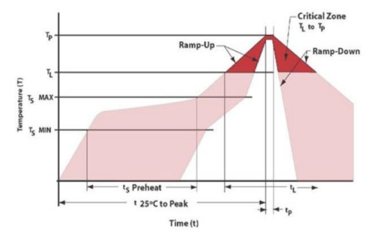
Figure 14: Convection Reflow Soldering Profile, per IPC/JEDEC J-STD-020
Table 11: Lead-Free Process Classification Temperature (Tc)
| Package Thickness |
Volume, mm3 < 350 |
Volume, mm3 350 - 2000 |
Volume, mm3 >2000 |
|---|---|---|---|
| <1.6 mm | 260°C | 260°C | 260°C |
| 1.6 to 2.5 mm | 260°C | 250°C | 245°C |
| >2.5 mm | 260°C | 245°C | 245°C |
Table 12: High Temperature Infrared/Convection Reflow Conditions IPC/JEDEC J-STD-020
| IPC/JEDEC Standard | IPC/JEDEC J-STD-020 |
| Moisture Sensitivity Level | Level 1 |
| TS MAX to TL (Ramp-up Rate) | 3°C/second Maximum |
Preheat
| Temperature Minimum (TS MIN) | 150°C |
| Temperature Typical (TS TYP) | 175°C |
| Temperature Maximum (TS MAX) | 200°C |
| Time (tS) | 60 - 180 Seconds |
| Ramp-up Rate (TL to TP) | 3°C/second Maximum |
Time Maintained Above
| Temperature (TL) 60 - 150 Seconds | 217°C 260°C Maximum for 10 Seconds |
| Time (TL) | 60 - 150 Seconds |
| Peak Temperature (TP) 60 - 150 Seconds | 260°C Maximum 260°C Maximum for 10 Seconds |
| Target Peak Temperature (TP Target) | 255°C |
| Time within 5°C of Actual Peak (tP) | 20 - 40 seconds |
| Max. Number of Reflow Cycles | 3; see Note 2 |
| Ramp-down Rate | 6°C/second Maximum |
| Time 25°C to Peak Temperature (t) | 8 minutes Maximum |
Note 1: Temperatures shown are applied to body of device.
Note 2: For 9.0 mm x 7.0 mm 10L stacked PCB package Max. Number of Reflow Cycles are 2.
Table 13: Manual Soldering Conditions
Manual Soldering (Iron)
| 350°C Maximum for 3 seconds | Caution: Small package body parts heat up very quickly and can be damaged. Proper baking needs to be done prior to manual soldering/desoldering, if not stored as per Section 4, for MSL3 classified products to avoid device damage. |
7.2 PCB Cleaning Assembly Notes
Cleaning PCB assemblies after reflow is a common process requirement to remove residual flux and loose solder. No-Clean and water-soluble fluxes are left behind and require removal to meet assembly inspection standards. The package materials of the SiTime products are not susceptible to water or other common solvents (alcohol and acetone) used for assembly cleaning. SiTime recommends not using cleaning and manufacturing equipment (e.g., ultrasonic plastic fusion, plastic saw, plastic test machines, cleaning baths) operating at ultrasonic frequencies. Instead, SiTime recommends that the customer use IPA (Isopropyl Alcohol) baths.
SiTime products, which are in WLCSP package, include a protective, opaque polymer topcoat. If the part will be exposed to intense light, especially in the 1.0-1.2 µm IR spectrum, we recommend a protective “glob-top” epoxy or other cover to keep the light from negatively impacting the frequency stability.
One of the key elements enabling extremely stable MEMS resonators is the SiTime EpiSeal® process which hermetically seals the resonators during wafer processing, eliminating the need for hermetically sealed ceramic packaging. The SiTime EpiSeal resonator is impervious to the highest concentration elements in the atmosphere, nitrogen, and oxygen, and therefore acts as a perfect seal. Previous generations of EpiSeal resonators may have been impacted by large concentrations of small-molecule gas. Newer EpiSeal resonators are impervious to all small-molecule gases. Please contact SiTime for recommended gas-impervious parts for applications where SiTime parts may be exposed to a large concentration of small-molecule gas.
8. Product Packing
8.1 TNR Packing in Inner/Pizza Box
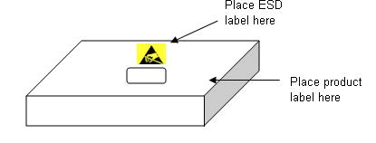
The sealed reel is placed in a static dissipative ESD bag. An ESD label and product label is placed on the ESD bag. One reel/ESD bag is wrapped in anti-static bubble wrap and placed in an inner box/pizza box (Figure 15). Pizza Box packing flow is shown in Figure 16. Desiccants and HICs (humidity indicator cards) are not included for MSL1 products.
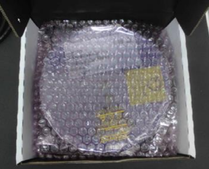
Figure 15: ESD Bag Packing in Inner Box

Figure 16: Inner Box/Pizza Box Packing Flow
8.2 Pizza box/Inner box dimensions are provided below
Table 14: Thick Pizza Box Dimension - Tolerance 20 mm
| Reel size | Length (L) | Width (W) | Height (H) |
| 7 inch reel | 220 mm | 205 mm | 50 mm |
| 13 inch ree | 370 mm | 355 mm | 55 mm |
Table 15: Thin Pizza Box Dimension - Tolerance 5 mm
| Reel size | Length (L) | Width (W) | Height (H) |
| 7 inch reel | 220 mm | 205 mm | 35 mm |
| 13 inch ree | 346 mm | 346 mm | 35 mm |
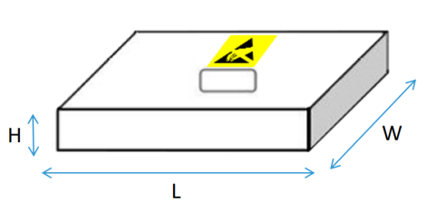
Figure 17: Pizza Box dimensions
8.3 Packing pizza boxes in shipping carton
All pizza boxes will be placed vertically in the shipping carton. Each shipping carton will have the maximum number of pizza boxes which will fit in the carton. Antistatic bubble wrap or popcorn will be used as filler for empty space.
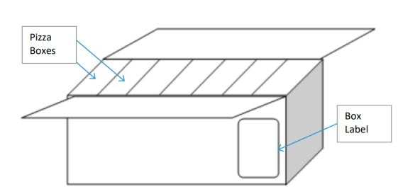
Figure 18: Shipping Carton Packing
9. Package Labeling
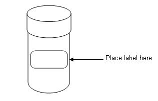
9.1 Canister Label
Label size will be 2.0” x 4.0”.
Each canister will only have one label.
Each label will only contain lot detail of 1 manufacturing lot determined by the trace code.
The canister labels will contain the following un-bar coded information.
Company Name: SiTime
| RoHS symbol: | ESD symbol: |
 |
 |
The canister labels will contain the following bar coded information.
Lot Code: SiTime lot code identified on the test release request (TRR). Ignore the first 2 digits from the lot code and print only the next 5 or more from the lot number which should appear on the label. The lot number should not have the split lot information or any other additional characters used by the vendor for their internal flow.
For example:
The split lot number 1AA00LU_01 or 1AA00LU@re or 1AA00LU@cr. The lot number on the label should be A00LU.
Device: SiTime marketing part number identified on the TRR or ABR.
Marketing Part Number: SiTime marketing part number identified on the TRR or ABR.
Date Code: Product manufacturing date code.
Quantity: Quantity of units in the canister.
Additional information: 2D barcode usage is an option for suppliers to use, for their internal manufacturing traceability process only.
9.2 Pizza Box Label
Pizza box label will contain the same information as the canister label except for tape and reel batching reel. Sitime allow having either 2 lot numbers and/or 2 date codes. The lots from different packaging assembly house or lot from different wafer foundry or lot from different wafer part number cannot be combined into a reel. The quantity for both lots needs to be specified clearly. See example below.
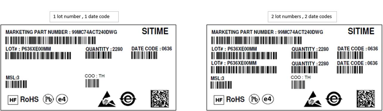
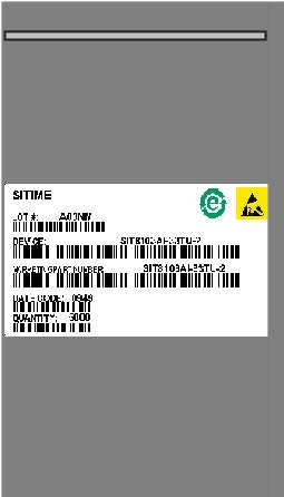
Figure 19: Inner Box/Pizza Box Label
| Field Name / Logo | Description |
| MARKETING PART NUMBER | SiTime Marketing Part Number |
| LOT# | SiTime Lot Number |
| QUANTITY | Quantity in the reel/ container/inner box |
| LOT# | SiTime Lot Number |
| DATE CODE | Date Code(s) in “YYWW” format (“YY” denotes 2-digit year and “WW” denotes 2-digit work week. |
| COO | Country of Assembly - 2-digit ISO code. |
| MSL | Moisture Sensitivity Level |
| HF | Halide Free Logo - Indicates if the material is Halide Free |
| Material Category Symbol | Follow IPC/JEDEC J-STD-609, 5.3.2 Pb-free categories. |
| RoHS | RoHS logo - Indicates if material complies with Europe RoHS |
| Pb | Pb Free logo - Indicates if the material is Lead Free |
| 2D Barcode | It is an option for suppliers to use, for their internal manufacturing traceability process only |
9.3 Outer Box / Carton Labeling
The outer box/carton label is shown in Figure 19.
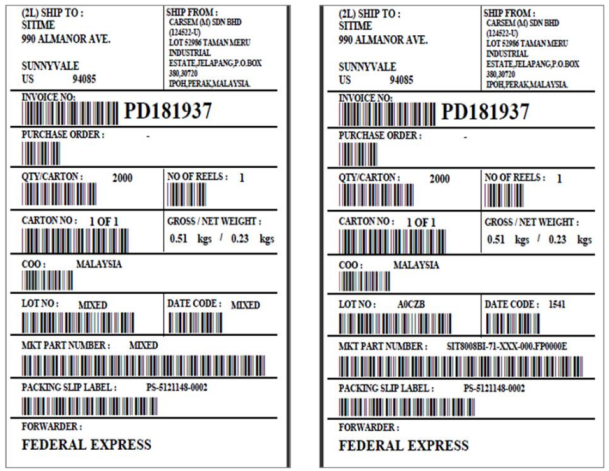
Figure 20: Outer Box/Carton Label
Where,
- Label size will be 4.0” x 6.0”
- Label will contain the following information:
i. Ship to
ii. Ship from
iii. Invoice no – optional field (vendors internal reference)
iv. End customer PO number
v. Total Box Quantity
vi. Number of reels
vii. Number of Carton (s)
viii. Gross and Net Weight
ix. Country of Origin (COO)
x. Lot Number
xi. Date Code
xii. Marketing Part Number
xiii. Packing Slip Label No
xiv. Forwarder Information
Note: When there is more than one marketing part number or more than one date code or more than one lot code, these fields will be indicated as “MIXED” on the label.
9.4 Label Placement
Canister label: 1 label per canister. Label to be placed around the canister.
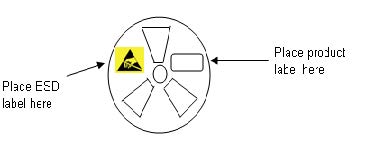
Pizza box label: One label per box. Label is to be placed on top portion of the pizza box. If the box has a pre-printed ESD symbol already on the box, then the ESD label is not required.
Lock reel label: Lock reel label will contain the same information as the pizza box label.
Tube label: 1 label per MBB or conductive bag. Label to be placed in the middle of the bag.
ESD label: 1 label per bag. Label to be placed in the middle of the bag.
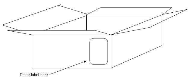
Shipping carton label: Min 1 label per shipping carton.
10. Additional Questions?
If you have any questions about the information contained in this manufacturing note or other manufacturing questions, please contact your sales representative.