Pushing the performance boundaries of optical modules with timing technology
The deployment of 5G networks will enable tremendous advancements in communications – increasing bandwidth 10-fold and reducing latency by 50 times. To achieve such massive improvements, several technologies are pushed to evolve at a rapid pace including equipment and components used in datacenters. Optical transceivers, responsible for connecting and translating data carried over optical fiber into electrical signals within the datacenter, are one example.
Data Centers & Optical Modules
To handle the vast increases in data traffic, the transmission rates of optical modules is doubling and in some cases quadrupling. In 2020, 100 gigabit per second (Gbps) data rate modules are commonly used. However, the use of 400 Gbps modules is rapidly increasing and 800 Gbps modules are now in development. Higher-capacity 400 Gbps and 800 Gbps networks are placing greater demands on optical modules and the oscillators within them. These devices must have greater functionality with denser designs, lower power per bit, and tighter jitter than their predecessors.
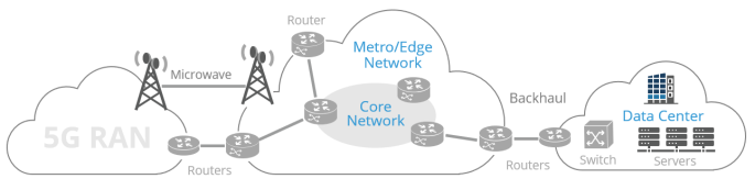
Figure 1: Optical modules are used at every point across the optical backbone—from the fronthaul to the backhaul—with high-data-rate transceivers required in metro networks and datacenters
Hyperscale datacenters are one of the largest drivers of increased optical throughput. 5G requires the transmission and computing of massive amounts of data. To accommodate this, datacenters must employ higher capacity optical modules. However, data centers are space limited and expensive to expand, meaning that optical modules must double or quadruple their data rate while minimizing additional size.
Additionally, the power needed to operate datacenters is extraordinary. Some industry experts expect datacenters to account for as much as eight percent of global electricity consumption by 2030[1]. Optical modules are expected to make vast improvements in throughput with little extra power required. Datacenters, in addition to other high-bandwidth data communications applications, are pushing the boundaries of optical module technology and by extension, placing greater requirements on oscillator technology.
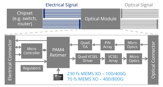
Figure 2: Optical module block diagram with a SiTime low-jitter MEMS oscillator clocking the PAM4 retimer
The role of an optical module is to convert incoming optical signals into electrical signals, and conversely transform outgoing electrical signals back to the optical format for transport without introducing errors. This poses the complex problem of synchronizing the two time domains, that of the optical network and that of the chipset on the host board. This makes accurate timing one of the most critical factors within an optical module. The component that is responsible for bridging the timing gap, aptly named the retimer, requires a reference clock that must have increasingly lower jitter as the data-rate increments from 100 to 400 and 800 Gbps.
Watch video: MEMS timing solutions for optical modules
As 400 gigabit modules are beginning deployment, phase jitter of the reference oscillator is becoming ever more critical. RMS phase jitter is typically computed by integrating phase noise over 12 kHz to 20 MHz offset frequencies. SiTime’s SiT9501 differential oscillator starts with a phase noise of just -89 dBc per Hertz and ends with a noise floor of -170 dBc per Hertz. When integrated, the tight phase noise translates to an RMS phase jitter of 70 femtoseconds for a 156.25 MHz clock frequency. Oscillator RMS phase jitter quantifies the variation of a clock edge. RMS phase jitter in reference clocks driving optical modules is particularly important because it adds to jitter in the serial data stream passing through the module and can create errors if this jitter is too large. As throughput doubles from 400 Gbps to 800 Gbps, the jitter in the signal should reduce proportionally by a factor of two to maintain a similar timing margin.
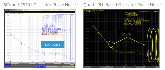
Figure 3: Comparison of phase noise between a SiT9501 MEMS oscillator (RMS jitter: 70.629 fsec; no spurs) and a quartz PLL-based oscillator (spurs).
Another important factor to consider when calculating phase jitter is the presence of spurious noise (spurs) in the phase noise. Referring to figure 3, the phase noise plots seem comparable at first glance, but with a closer look the spurs in the quartz-based phase-locked loop (PLL) oscillator become apparent. The phase noise of the SiT9501 oscillator has no spurs, leading to an RMS phase jitter of just 70 femtoseconds. Conversely, the quartz oscillator has a total RMS phase jitter of 267 femtoseconds. When calculated without the spurs, the RMS phase jitter of the quartz oscillator is only 90 femtoseconds, meaning the spurs attribute to 60 percent of the total jitter. SiTime’s advanced integer-N PLL technology allows for tight phase noise and lower jitter without spurs.
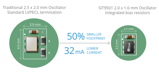
Figure 4: Comparison of footprint and current consumption of traditional AC-coupled LVPECL layout with a 2520 oscillator (left) and layout of a 2016 SiT9501 device with integrated LVPECL source-bias resistors (right).
SiTime's Differential Oscillator Designs
While optical modules are driven to increase data rates by two to four fold, the components included in the module need to deliver these improvements without increasing their footprint. SiTime’s SiT9501 differential oscillator is the optimal solution for 400 Gbps and 800 Gbps designs as it requires no compromise in performance for smaller size with only 70 femtoseconds of RMS phase jitter. Furthermore, the SiT9501 oscillator (in a 2.0 x 1.6 mm package) integrates source-bias resisters leading up to a 50 percent reduction in the total footprint compared to leading 2.5 x 2.0 mm quartz oscillators.
The SiT9501 oscillator also integrates on-chip voltage regulators which filter power supply noise and improve the power integrity in module designs. Reducing the timing footprint with such integrated features and small package size is important because over half of the optical module is consumed by the laser sub-assembly and its associated electronics, leaving little room for the signal processing and data path. Any space savings allows module makers to pack in other features.
To address the strict current limitations imposed on optical modules, the removal of the two bias resistors leads to 32 milliamps lower current consumption with an AC-coupled output. The SiT9501 also introduces FlexSwing™ technology that uniquely enables the differential voltage swing to be custom programmed at the factory to comply with the differential input-swing requirements of any chipset. FlexSwing allows engineers to accommodate low-voltage chipsets with non-standard voltage swings. By matching the precise needs of the chipset, the typical termination can be eliminated, reducing power by up to 16 milliamps with a DC-coupled LVPECL output.
The evolution of optical modules to 400 Gbps and 800 Gbps data rates, driven by emerging technologies, demands leaps in performance without increases in size and current consumed. This in turn is driving oscillators to be more power efficient, consume less space, and provide lower jitter. With innovations such as integrated bias resistors and programmable voltage swing, SiTime’s SiT9501 differential oscillator delivers reductions in total footprint and current consumption, all with just 70 femtoseconds of RMS phase jitter. SiTime MEMS oscillators provide an innovative timing solution that meets the needs of optical module makers that must quickly scale performance to support rapid advancements in network equipment.
.............................................................
Reference:
[1] Jones, Nicola. “How to Stop Data Centres from Gobbling up the World's Electricity.” Nature News, Nature Publishing Group, 12 Sept. 2018, www.nature.com/articles/d41586-018-06610-y.
.............................................................
Learn more: