Jitter 101. What you need to know.
Our increasingly connected world and demand for more data requires faster data-communication rates, where timing jitter occupies a larger portion of a system's overall timing budget. To keep up with increasing bandwidth, each new generation of technology must conquer the effects of jitter. To do so, it’s important to understand the concept of jitter, the different types of jitter, what causes it, and how to measure it.
In this blog, we define the three most common types of jitter and provide valuable resources for a deeper understanding. We also provide tips for learning about measurement methods, and handy calculator tools for converting, estimating and computing different types of jitter.

What is jitter?
In simple terms, jitter is a variation of a timing event. It is the deviation of a set of signal edges from their ideal values. There are many ways to define jitter and at least nine types of jitter the electronics industry is concerned about. Below are descriptions of the three most common types of jitter, which are period jitter, cycle to cycle jitter, and time-interval error (TIE) jitter. Note there are many standards in the industry and there are slightly different definitions of jitter depending on the standard. If you are working within a specific standard, you need to understand how that standard defines jitter even though they may use the same terminology as other standards.
Jitter can be caused by a number of reasons. Here are some common causes:
- Thermal noise
- EMI from an external source such as a switching power source
- Crosstalk
- Lossy medium
- Voltage droop and ground bounce
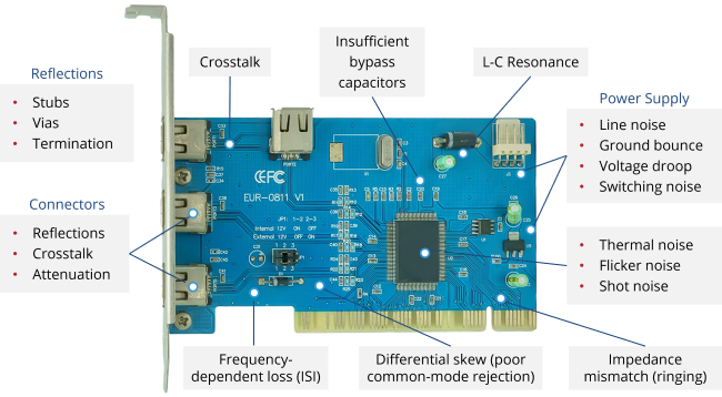
Typical sources of jitter
Attend our Jitter Fundamentals on-demand course to get a deeper understanding of the sources of jitter and tips for minimizing jitter sources.
Period jitter
Period jitter is fairly simple to understand. It is defined in JEDEC Standard JESD65B as the variation of any one waveform period from its average value. It is the deviation in cycle time of a clock signal with respect to the ideal period over a number of randomly selected cycles. Shown under the wave form below is the equation of how to calculate period jitter.
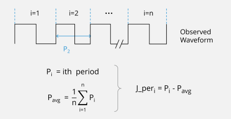
Period jitter measures the variation of a period from its mean value.
Cycle to Cycle (C2C) Jitter
C2C jitter is defined in JEDEC Standard JESD65B as the variation in cycle time of a signal between adjacent cycles, over a random sample of adjacent cycle pairs. Shown under the wave form below is the equation for calculating C2C jitter is shown under the waveform below. Take our 32-minute Jitter Fundamentals on-demand course to learn more about important caveats in calculating C2C jitter.
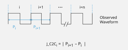
Cycle to cycle jitter, highlighted by the blue arrows, shows variation between two neighboring cycles.
Jitter application notes
Clock Jitter Definitions and Measurement Methods – Learn more about different types of jitter encounter in today’s high-speed systems, plus best practices for measuring jitter using a real time oscilloscope in this application note.
How to Setup a Real-time Oscilloscope to Measure Jitter – One of the most common instruments used to measure jitter is the real-time digital oscilloscope. This application note provides guidelines for setting up an oscilloscope for best jitter measurement accuracy.
Removing Oscilloscope Noise from RMS Jitter Measurements – Learn how to accurately measure jitter using a real-time oscilloscope when the level of jitter added to a signal from the measurement environment approaches or exceeds the signal's intrinsic jitter.
Time interval error (TIE) jitter
TIE jitter is the variation of an edge with respect to a reference waveform edge. It is the short-term variation of the significant instances of a digital signal from its ideal position in time. TIE is the most complicated form of jitter between the three types. To properly analyze TIE, you need a reference waveform, which is one of the reasons that make TIE jitter more complex.
Shown under the waveform below is the equation for calculating TIE jitter. Attend our Jitter Fundamentals on-demand course where we discuss more details and go through a thought experiment to build insight into how TIE is calculated.
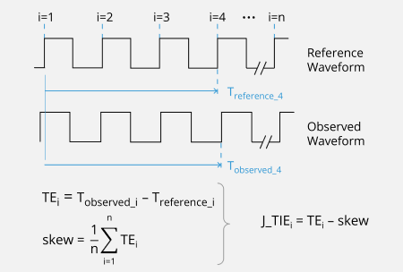
Time interval error (TIE) jitter is the variation of an edge with respect to a reference edge.
TIE jitter application notes
Computing TIE Crest Factors for Telecom Applications – Learn how to compute crest factors using a procedure used in the telecom industry for applications that generally revolve around standards such as SONET, SDH, and OTN.
Computing TIE Crest Factors for Non-telecom Applications – This note presents two common methods for computing TIE crest factors and are aimed for applications that employ a range of non-telecom standards such as Fibre channel, PCI Express, Ethernet and more.
Now that we've defined three common types of jitter, it’s important to recognize that just because a certain type of jitter appears on a datasheet, it doesn’t mean it applies to your application. It is the application, and not the datasheet, that determines the type of jitter required. For any particular type of interface, there are usually only one or two types of jitter that are important for that interface. The other types of jitter aren’t important. So don’t rely on what’s in the datasheet. Instead understand what type of jitter is important for your application.
Our Jitter Fundamentals on-demand course explains more about what type of jitter is used for which application, including those listed below. And more importantly, why.
- Data converters
- Synchronous logic
- Phase locked loop (PLLs)
- Parallel buses
- Serial bus transmitter
- Parallel versus serial bus
Jitter is a complex but important topic. It must be understood and measured in today’s high-speed systems. Below are additional learning resources and tools. If you want more help understanding jitter in your application, Contact SiTime.
Free on-demand courses on jitter
The Timing Essentials Learning Hub is designed for working professionals with classes focused on the practical application of theory and providing a deeper understanding of how timing can impact performance in your next design.
- Jitter Fundamentals
- Clock Jitter in High-speed Serial Links
- How PLLs Filter Jitter
- Understanding Precision Oscillator Specifications
- Common Timing Issues and Solutions
4-minute clinic:
Determine the Dominant Source of Jitter by Inspection of Phase Noise PlotWant to know where best to spend your resources to improve your electronic design? Watch to learn how to analyze a phase noise plot and understand the dominate source of jitter by inspection.
Jitter calculators
Jitter Calculator – Convert phase noise to phase jitter (rms) for a specified offset frequency range. Plot phase noise data and export results as a png, csv or PDF file.
Jitter Budget Spreadsheet Calculator – Estimate total jitter by connecting several elements in series, given each element's random and deterministic jitter contribution. Alternatively, begin with a jitter target, then budget jitter for each element to meet this target.
RMS to Eye-closure Jitter Calculator – Computes the eye-closure in a BER bathtub plot due to the random component of TIE jitter (in ps rms) in a signal. Alternatively, calculate a crest factor for your specific application.
RMS to Peak-peak Jitter Calculator – Evaluate a jitter distribution at a specified probability to convert an rms value of jitter into a peak-to-peak value. A quick reference table is also provided to estimate probabilities.
Phase Noise Spreadsheet Calculator – Calculate phase jitter from measured phase noise data, including jitter filtering. Plus, learn all the math behind these calculations.