Considerations for Measuring Phase Noise in Differential Oscillators
Contents
1. Introduction
2. Key Considerations
3. Conclusions
4. References
1. Introduction
SiTime's differential oscillators feature excellent phase jitter performance for their respective class of products. For example, the SiT9501 oscillator features 70 fs rms of phase jitter, measured by integrating phase noise over an offset-frequency range of 12 kHz to 20 MHz. SiTime's differential oscillators employ a differential output driver with excellent power-supply noise rejection and an ultra-low output-noise floor. The differential driver also reduces common-mode noise sources internal to the device and power supply noise, as illustrated in Figure 1, leading to better than -170 dBc/Hz at a 156.25 MHz clock frequency for the SiT9501. This document describes test methodologies to measure the true performance of the following ultra-low jitter devices using differential measurements.
- SiT9501 – 70 fs phase jitter (rms)
- SiT937x – 200 fs phase jitter (rms)
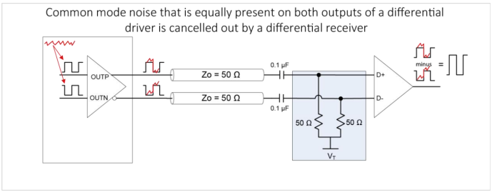
Figure 1: Common-mode noise cancellation in differential signaling
2. Key Considerations
When measuring phase noise using an instrument with only a single-ended input, such as a spectrum analyzer and phase noise analyzer (e.g. Keysight Technologies E5052B Signal Source Analyzer), it is often convenient to connect one of the differential outputs to the equipment and apply a dummy termination to the other output to balance the load (Figure 2). This approach often yields acceptable results but in a low-noise device the phase noise measurement may suffer a few dB of noise floor degradation at offsets above 10 MHz. As illustrated in Figure 2 this is due to the fact that common mode noise cannot be canceled out in a single-ended receiver and will be measured by the instrument as part of the signal under test. Since a receiver in the end application is differential, the single-ended measurement diagram shown in Figure 2 introduces errors compared to the actual device’s performance in the application.
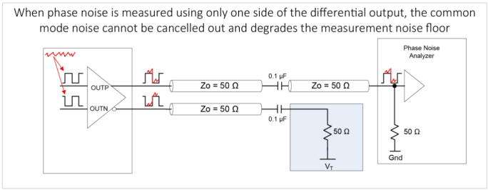
Figure 2: Common mode noise affecting measurement noise floor in single-ended measurement
To resolve this issue, it is recommended to use a balanced-unbalanced (balun) transformer to convert a differential signal into a single-ended signal without performance degradation (Figure 3). This balun takes the differential input and produces a single-ended output that is the difference between OUTP and OUTN. Common-mode noise present on individual conductors of a differential-pair get attenuated inside the balun.
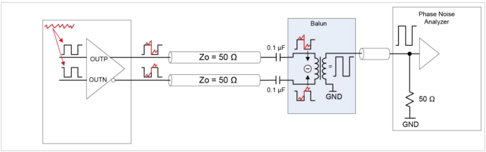
Figure 3: A balun is recommended to measure phase noise in differential devices when connecting to an instrument with a single input
Figure 4 compares single-ended (Figure 2) with differential measurements using a balun (Figure 3). Because the noise floor at offsets above 20 MHz approaches that of the E5052B signal source analyzer, it’s important to use cross-correlation to remove instrument noise and observe the true phase noise of the SiT9501. Using an instrument such as the E5052B with cross-correlation features can cancel instrument noise. The amount of noise cancellation depends on the number of correlations. For example, 100 times correlation can produce a 10 dB phase noise sensitivity improvement.[1] A cross-correlation value of 64 was sufficient to observe the SiT9501 performance when starting the E5052B measurement at a 100 Hz offset frequency. The overall 12 kHz to 20 MHz integrated phase noise difference is 2 fs between the two cases. More importantly, the noise floor measured in single-ended mode is up to 2 dB higher at offsets above 20 MHz. For more information on cross-correlation and other phase noise measurement methods, plus recommendations on setting up and connecting to an analyzer, refer to AN10062 Phase Noise Measurement Guide for Oscillators.
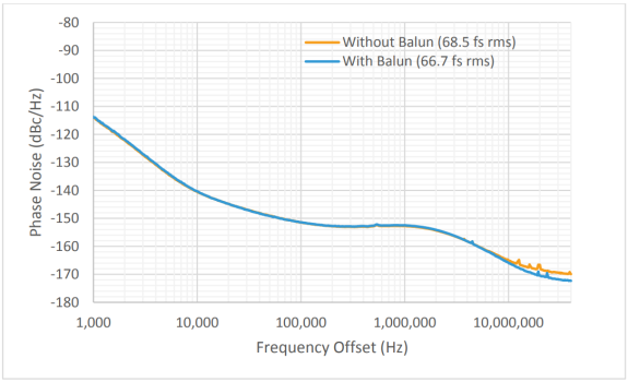
Figure 4: SiT9501 156.25 MHz LVPECL phase noise data measured by optimally-set E5052B instrument (cross correlation = 64) comparing single-ended (orange curve) versus differential measurements using a balun (blue curve).
3. Conclusions
Measuring the true phase noise of SiT9501 and SiT937x differential oscillators is best achieved using a balun to remove common-mode noise when measuring with a phase noise analyzer, to observe the same performance as observed by a differential receiver. Additionally, for devices that have an ultra-low phase noise floor, such as SiT9501, implementing cross-correlation in the phase-noise analyzer, e.g., E5052B, can further improve the measured phase noise at far-offset frequencies.
4. References
[1] Keysight Technologies, “E5052B Signal Source Analyzer” Technical Overview, December 26, 2019, pp 7