1 Introduction
Semiconductor components are expected to perform reliably over the lifetime of the product. Choosing devices with the highest reliability ratings limits the likelihood of faulty components causing product failure in the field. SiTime provides oscillators that meet this goal, with zero MEMS field failures over 250 million units (as of January 2015).
Zero field failures is impressive, but engineers want assurance that parts have been adequately tested for reliability. The key metric for gauging reliability of semiconductor components is mean time between failure, or MTBF. The higher the MTBF, the longer the expected lifetime of the device and therefore the more reliable the device. This application note describes the testing process and calculations of predicted MTBF for SiTime MEMS oscillators.
2 Accelerated testing
The predicted MTBF for semiconductor components is the inverse of the failures in time (FIT) rate, which is the number of failures statistically expected after one billion operating hours. It is obviously not realistic to test devices for one billion hours, so the common approach is to conduct accelerated testing at elevated temperature and voltage (burn-in) for a shorter number of hours and extrapolate.
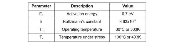
SiTime conducted burn-in testing in a chamber set to an industry standard temperature of 125°C. However, due to heat dissipation when the part is powered up, there is typically a five-degree rise in junction temperature during stress testing and during operation. This is factored into the values in Table1. The acceleration factor due to temperature, AFT, follows an Arrhenius relationship and is calculated in reference to standard operating temperature using equation 1.

Table 1. Parameter values for acceleration factor due to temperature
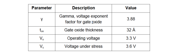
Nominal operating voltage for the tested SiTime oscillators is 3.3 volts. Stress testing was conducted at a power supply voltage to 3.6 volts, or about 10 percent above nominal voltage. The acceleration factor due to voltage, AFV, is calculated using equation 2, with the parameters as specified in Table 2.

Table 2. Parameter values for acceleration factor due to voltage
3 Results for SiTime Oscillators
SiTime stress tested thousands of oscillators for a cumulative test time of 3,307,000 device hours with no failures. Using statistical methods it is possible to predict the number of failures after one billion hours with a certain degree of confidence, using equation 3, where n is the number of device hours of burn-in testing.

For a 90 percent confidence level of zero fails, the χ2 statistic has a value of 4.6. Plugging into equation 3 results in a FIT0 rate of 696.3. It is now necessary to correct for accelerated test conditions using the acceleration factors from equations 1 and 2. The adjusted final FIT rate is given by equation 4.
Using the values in Tables 1 and 2 to calculate the acceleration factors and the FIT0 value above, the final FIT for SiTime oscillators is:
The MTBF is the inverse of the FIT rate, expressed in billions of hours. For the FIT rate calculated above, MTBF is about 1140 million hours or over 130,000 years. This greatly exceeds reported MTBF for competing quartz-based oscillators, as shown in Figure 1.
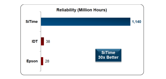
Figure 1. Reliability of SiTime MEMS-based and quartz-based oscillators in terms of MTBF
4 Conclusions
SiTime reliability testing demonstrates a FIT rate of less than 0.9, corresponding to MTBF of 1140 million hours. This is a factor of 30 times better than MTBF of quartz oscillators, making SiTime MEMS oscillators the most reliable oscillators on the market.
Other reliability and resiliency application notes on SiTime oscillators
SiT-AN10045 Resilience and Reliability of Silicon MEMS Oscillators
SiT-AN10032 Shock and Vibration Comparison of MEMS and Quartz-based Oscillators
SiT-AN10031 Electromagnetic Susceptibility Comparison of MEMS and Quartz-based Oscillators
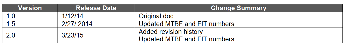
Revision History