TCXO and OCXO Stability Degradation
Contents
1. Introduction
2. Stability Degradation of Quartz-Based TCXOs and OCXOs
3. System Impact
4. Conclusion
Appendix
1. Introduction
Many digital applications rely on cooling systems to maintain the operating temperature within design limits, which are typically -40°C to +85°C for industrial applications. But cooling systems can fail, for example if the fan malfunctions, and this can cause the ambient temperature to increase above system design limits, in some cases to extreme values up to or in excess of +125°C. Ideally, systems should maintain normal operation during these fault conditions. Sustaining continuous operation can be critical for many systems, for example with cellular base stations which should maintain basic service to support emergency calls. Therefore system designers should choose components to achieve maximum reliability.
One of the most vitally important components of any digital system is the oscillator. It provides the synchronization signal for the entire system and is therefore sometimes referred to as the “heartbeat of the system.” Just like the heart in the human body, malfunction of the oscillator will cause the entire system to fail.
Automotive-grade crystal oscillators (XO), which can operate up to +125°C and meet the requirements of many applications, are commonly available. But precision oscillators such as temperature controlled crystal oscillators (TCXOs) and oven-controlled crystal oscillators (OCXOs) that operate above +85°C are rare and very difficult to find. For certain applications, such as Synchronous Ethernet (SyncE), IEEE 1588, and telecom boundary/slave clocks that provide backhaul service to cellular base stations, it is important to understand how such devices behave outside their rated temperature range in order to determine to what extent the system can maintain service during fault conditions.
To this end, this application note provides data and analysis of various TCXO and OCXO behavior at temperatures that exceed +70°C/+85°C, testing devices based on two technologies: MEMS (microelectro mechanical systems) and traditional quartz.
2. Stability Degradation of Quartz-Based TCXOs and OCXOs
SiTime MEMS-based TCXO and OCXO devices and quartz-based TCXO and OCXO devices were tested outside the upper temperature limit to investigate their behavior. TCXO devices rated to +85°C were tested to +125°C; devices rated to +70°C were tested to +105°C. OCXO devices rated to +85°C were tested to +105°C.
Figures 1-2 and Figures 5-6 show stability results for TCXO devices. The stability of quartz-based devices rapidly degrades just outside the rated temperature limit. The rate of frequency change increases from 10 ppb/°C between +85°C and +95°C to almost 3000 ppb/°C at +125°C (see figures 3-4 and 7-8). In contrast, the MEMS-based SiTime Elite Platform™ Super-TCXO™ device (SiT5356) gracefully changes frequency with a frequency verses temperature slope (ΔF/ΔT) better than 2 ppb/°C up to +105°C and increasing to only 8 ppb/°C at +125°C. The total frequency change from +85°C to 125°C is only 50 ppb.
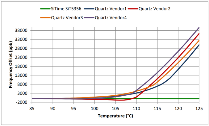
Figure 1: TCXO stability from +85°C to +125°C. Values are referred to the frequency offset at +85°C.
DUT: 5 industrial temperature rated TCXO devices.
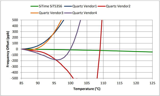
Figure 2: TCXO stability from +85°C to +125°C. Values are referred to the frequency offset at +85°C.
DUT: 5 industrial temperature rated TCXO devices. Horizontal zoom-in.
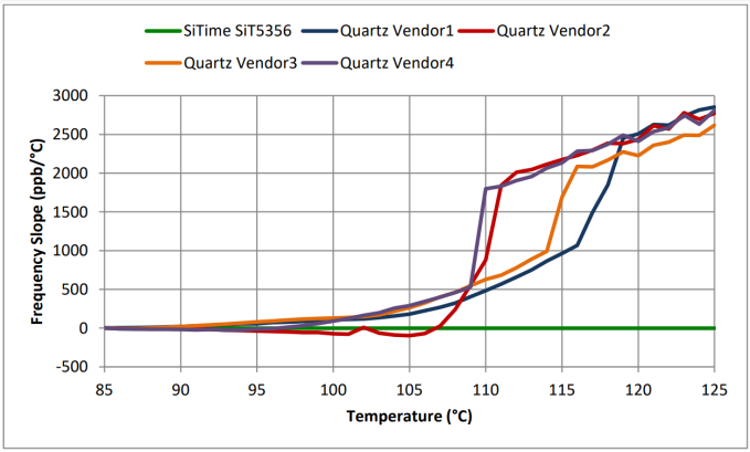
Figure 3: TCXO frequency versus temperature slope from +85°C to +125°C. Values are referred to the frequency offset at +85°C. DUT: 5 industrial temperature rated TCXO devices.
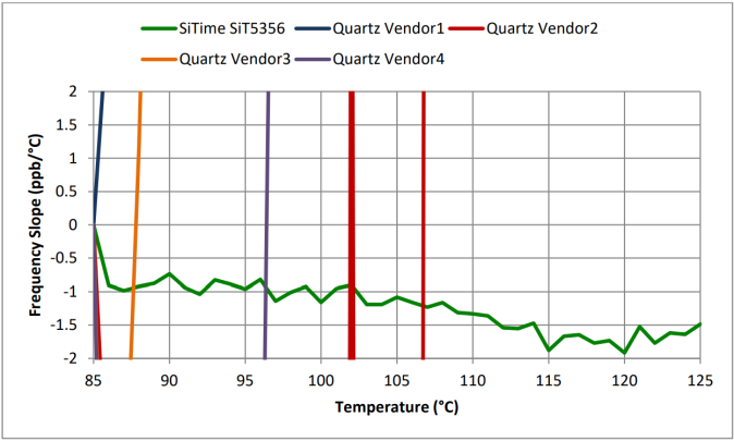
Figure 4: TCXO frequency versus temperature slope from +85°C to +125°C.
DUT: 5 industrial temperature rated TCXO devices. Horizontal zoom-in.
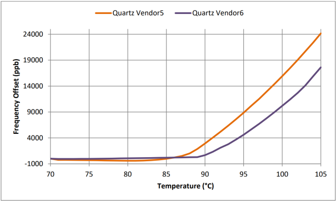
Figure 5: TCXO stability from +70°C to +105°C. Values are referred to the frequency offset at +70°C.
DUT: 2 commercial temperature rated TCXO devices.
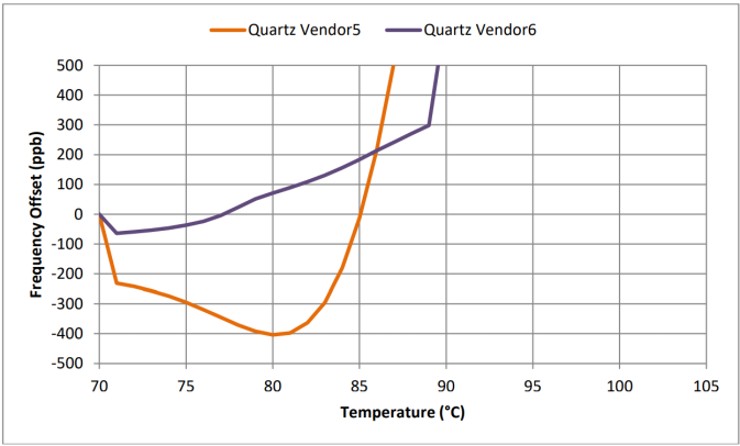
Figure 6: TCXO stability from +70°C to +105°C. Values are referred to the frequency offset at +70°C.
DUT: 2 commercial temperature rated TCXO devices. Horizontal zoom-in.
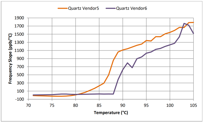
Figure 7: TCXO frequency versus temperature slope from +70°C to +105°C.
DUT: 2 commercial temperature range TCXO devices.
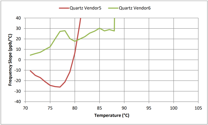
Figure 8: TCXO frequency versus temperature slope from +70°C to +105°C.
DUT: 2 commercial temperature rated TCXO devices. Horizontal zoom-in.
A similar behavior is observed when testing OCXO devices (see figures 9-10). The stability of quartzbased devices starts to degrade after the temperature goes outside the rated temperature range by 4°C to 8°C. The ΔF/ΔT degrades from 3 ppb/°C to 30 ppb/°C (see figures 11-12). In contrast, the MEMSbased SiTime Emerald Platform™ OCXO (SiT5711) devices maintain their rated stability up to +105°C with less than 0.5 ppb/°C frequency slope.
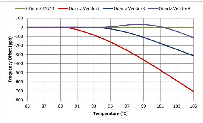
Figure 9: OCXO stability from +85°C to +105°C. Values are referred to the frequency offset at +85°C.
DUT: 4 industrial temperature rated OCXO devices.
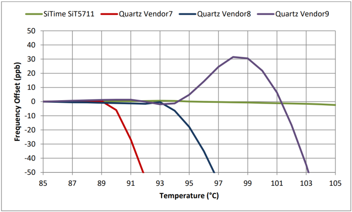
Figure 10: OCXO performance from +85°C to +105°C. Values are referred to the frequency offset at +85°C.
DUT: 4 industrial temperature rated OCXO devices. Horizontal zoom-in.
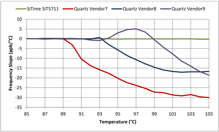
Figure 11: OCXO frequency versus temperature slope from +85°C to +105°C.
DUT: 4 industrial temperature rated OCXO devices.
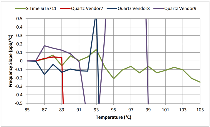
Figure 12: OCXO frequency versus temperature slope from +85°C to +105°C.
DUT: 4 industrial temperature rated OCXO devices. Horizontal zoom-in.
Please refer to the Appendix for more data on quartz-based devices and SiTime MEMS-based devices.
3. System Impact
TCXOs and OCXOs are high-precision devices with stability reaching 50-ppb level for TCXOs and 5-ppb level for Stratum 3E grade OCXOs. These devices are used in applications such as cellular base stations where a high-stability frequency reference is required and is critical for system performance. With cooling system failures and the possibility of the temperature rising above the operating temperature range, it is highly desirable to maintain some level of system functionality during these events. Besides covering fault cases, extended temperature operation of OCXOs and TCXOs may enable more reliable systems that don’t require cooling fans at all.
The test results shown in this application note clearly demonstrate that SiTime timing solutions are the best choice for fault tolerant and extended temperature systems. Quartz-based solutions rapidly loose stability if temperature goes outside their rated range. In the case of SyncE applications, this stability degradation can have several implications, depending on the severity of the degradation. For large ppm level degradations of the local oscillator, the PLL might unlock, leading to complete synchronization loss and system failure including dropped calls and data loss. Degradation of frequency stability also means comparable frequency slope increases. Local oscillator changes the frequency faster per 1°C of temperature variation. This means more error accumulates before it can be tracked by a low bandwidth PLL, like SyncE PLL. This leads to wander being out of spec and multiple slips in data transmission.
For IEEE 1558 applications this frequency slope degradation manifests as dynamic time error degradation. The time error accumulates faster than the low bandwidth IEEE 1588 loop can catch up and it exceeds the specifications. For base stations, this results in dropped calls or deterioration of call quality.
In general, rapid temperature increases due to cooling system failure will transform the high frequency versus temperature slope to high frequency versus time slope, and this will lead to malfunction for many systems. Synchronization applications, like SyncE and IEEE 1588 have a high-pass frequency response to system clock frequency changes, and rapid changes in the system clock frequency will not be tracked and will have an immediate deleterious effect on the SyncE PLL output frequency and overall system performance.
In contrast to quartz devices, SiTime MEMS-based Elite Platform Super-TCXOs and Emerald Platform Stratum 3E OCXOs have a graceful low-ΔF/ΔT change. Large frequency transients are avoided even with temperature changes. Low stability degradation can prevent system unlock and maintain performance within the time error specification even if operating outside the rated temperature range. This immunity to high temperature and rapid thermal change, combined with the inherent resilience against shock and vibration of SiTime MEMS oscillators, enable these timing solutions to maintain rated stability and provide continuous system operation.
4. Conclusion
The SiTime Elite Platform Super-TCXOs and SiTime Emerald Platform OCXOs demonstrate extreme resilience and robustness to environmental stressors such as shock, vibration, and rapid temperature changes. During these conditions, SiTime MEMS-based products maintain frequency stability and low ΔF/ΔT slope as the system temperature exceeds normal operating limits. This performance enables designers to build systems that can reliably operate at extended temperature ranges and provide continuous system operation even during malfunctions such as when cooling systems fail.
This robustness is becoming increasingly important in next-generation communications systems as 5G infrastructure will be deployed in outdoor and less-controlled rugged locations. SiTime’s robust timing technology will be the solution of choice because it excels in these environments.
Appendix
This appendix includes stability and frequency versus temperature slope data at temperatures above upper temperature limit across wider sample sets providing statistics and device-to-device variation data.
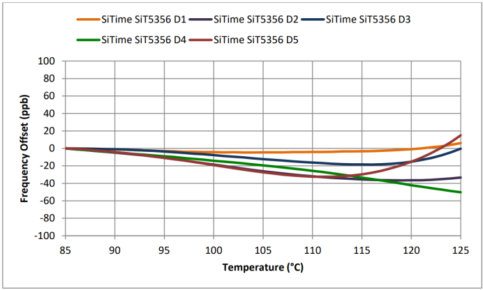
Figure 13: SiTime MEMS TCXO stability from +85°C to +125°C.
Values are referred to the frequency offset at +85°C. DUT: 5 SiT5356 devices.
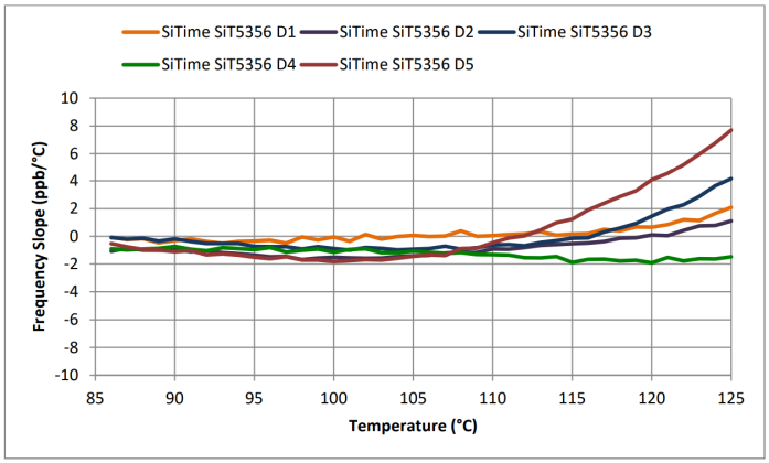
Figure 14: SiTime MEMS TCXO frequency versus temperature slope from +85°C to +125°C.
DUT: 5 SiT5356 devices.
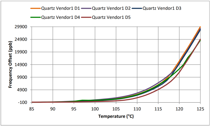
Figure 15: Vendor 1 quartz-based TCXO stability from +85°C to +125°C.
Values are referred to the frequency offset at +85 °C. DUT: 5 quartz TCXO devices from vendor 1.
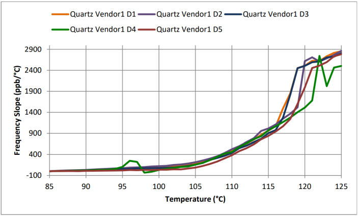
Figure 16: Vendor 1 quartz-based TCXO frequency versus temperature slope from +85°C to +125°C.
DUT: 5 quartz TCXO devices from vendor 1.
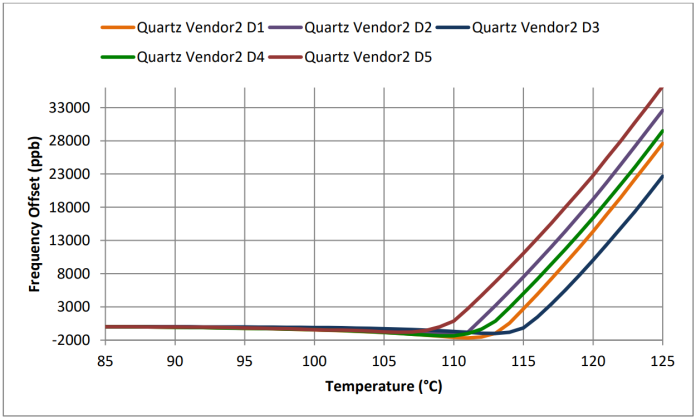
Figure 17: Vendor 2 quartz-based TCXO stability at +85°C to +125°C temperature range.
Values are referred to the frequency offset at +85°C. DUT: 5 TCXO devices from vendor 2.
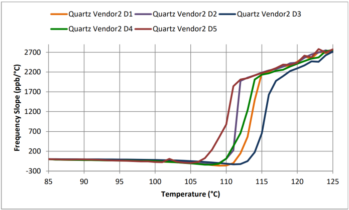
Figure 18: Vendor 2 quartz-based TCXO frequency versus temperature slope at +85°C to +125°C.
DUT: 5 TCXO devices from vendor 2.
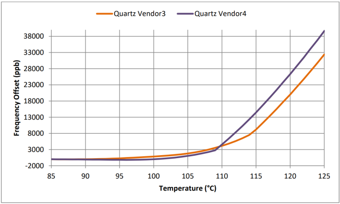
Figure 19: Vendor 3 and vendor 4 quartz-based TCXO stability from +85°C to +125°C.
Values are referred to the frequency offset at +85°C. DUT: 1 TCXO device from both vendors.
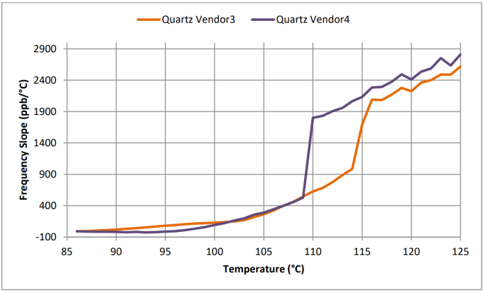
Figure 20: Vendor 3 and vendor 4 quartz-based TCXO frequency versus temperature slope from +85°C to +125°C.
Values are referred to the frequency offset at +85°C. DUT: 1 TCXO device from both vendors.