A Modern Approach to Refclk Jitter Analysis for SerDes Applications
In the fast-paced world of high-speed data communication, the importance of accurate reference clock (refclk) jitter analysis cannot be overstated. For decades, the industry has relied on a traditional method of analyzing refclk jitter using a 12 kHz to 20 MHz brick wall filter. However, with the advent of higher data rates and more complex systems, this method has become outdated, leading to suboptimal performance in modern SerDes serializer-deserializer (SerDes) applications.
In this article, we'll explore the limitations of the traditional methodology and introduce a new, practical approach that promises to enhance system performance and simplify refclk selection for SerDes applications.

The Evolution of Refclk Jitter Analysis—The Traditional Methodology
Since establishment in 1992, the traditional 12 kHz to 20 MHz filter used to analyze refclk jitter has been a cornerstone in the evaluation of timing components. This approach, originally developed to support the 2.488 Gbps data rate of SONET OC-48, integrates refclk phase noise over the specified frequency range to quantify phase jitter. For years, this method served the industry well, ensuring compatibility and performance across various applications.
However, the landscape of high-speed data communication has drastically changed since 1992. Modern systems operate at much higher data rates, and the jitter budgets have become increasingly stringent. The one-size-fits-all approach of the 12 kHz to 20 MHz filter is no longer sufficient to meet the diverse and specific requirements of today's high-speed SerDes applications.
Limitations of the Traditional Method for Refclk Jitter Analysis
The traditional methodology presents several critical issues:
- Incorrect Filter Corner Frequencies: The 12 kHz to 20 MHz filter is not universally applicable. Different applications have varying jitter filter requirements, and using a generic filter can result in inaccurate phase jitter budgets.
- Unrealistic Brick-Wall Filters: Real systems do not use brick-wall filters. Instead, they have filters with gradual roll-offs, which significantly contribute to the system’s total jitter.
- Aliased Phase Noise Ignored: Traditional analysis overlooks aliased phase noise, a significant factor in real systems. This omission can lead to significantly underestimating the actual phase jitter observed in practice.
- Significant Errors: Given the tighter jitter margins and higher data rates of modern systems, even small errors in jitter measurement (on the order of tens of femtoseconds) can have a substantial impact on performance today.

The arrows indicate the evolution of different standards over the years. Notice that the standards-defined high-pass filter (HPF) bandwidth increases with time, whereas the low-pass filter (LPF) bandwidth is usually defined by the SerDes vendor rather than standards. A key conclusion is that the error introduced by applying the traditional 12 kHz to 20 MHz methodology only increases with time.
These limitations necessitate a shift to a more precise and application-specific methodology for evaluating refclk jitter.
A New Methodology for Filtering Phase-Jitter
To address the shortcomings of the traditional method, we propose a more meaningful phase-jitter filter methodology. This approach, developed within the PCI-SIG Electrical Workgroup, involves using relevant application-specific jitter filters and accounting for phase-noise aliasing.
Implementing the New Methodology includes:
- Measure Phase Noise: Use a phase-noise analyzer, such as Keysight E5052B or Rhode & Schwarz FSWP, to measure the phase noise of the refclk. Avoid using spectrum analyzers or oscilloscopes for this measurement, as they can introduce significant instrument noise. For example, spectrum analyzers cannot separate amplitude noise from phase noise, which can lead to optimistic or pessimistic estimates of jitter depending on the signal’s slew rate and other factors.
- Extend Phase Noise Data: Extend the measured phase noise data flat to the third harmonic of the clock frequency. This step accounts for phase-noise aliasing that occurs in real systems when the refclk is sampled by the phase detector in the SerDes’s transmit phase-locked loop (PLL).
- Apply System Filters: Apply the system's jitter transfer function, including the appropriate filter roll-offs, to the phase noise data including the extension region. This accurately models the system's observed phase noise.
- Integrate Phase Noise: Integrate the filtered phase noise across offset frequency to derive the phase jitter value. This integration should begin at least an order of magnitude beyond the filter corner frequencies. Use free software such as SiTime Studio to automate this integration.
We recommend the clock and timing industry transition from the traditional 12 kHz-20 MHz brick wall filter to a more meaningful 4-16A filter when specifying phase jitter in datasheets. Here, 4-16A refers to a 4 MHz RX clock data recovery (CDR) bandwidth and a 16 MHz TX PLL bandwidth, both with first order roll offs (-20 dB/dec) and including aliasing (“A”) in the jitter calculation. This approach provides a conservative estimate of jitter performance for modern SerDes applications when the application is not specified. Alternatively, when the application is specified, then the appropriate application-specific filter should always be applied.
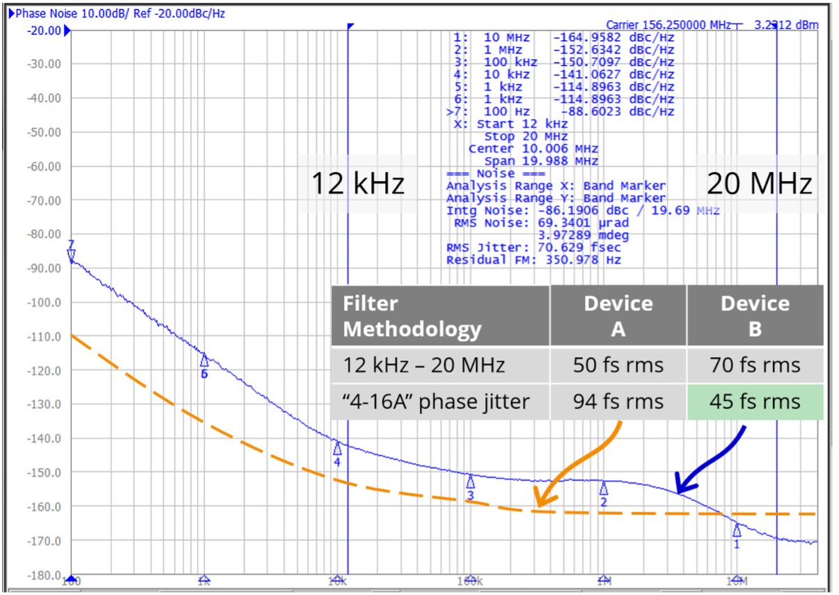
Two products analyzed with two different methodologies lead to opposite conclusions. The 4-16A phase jitter methodology more accurately predicts in-system performance for high-speed serial links versus the traditional method.
Following the above steps, the 4-16A methodology provides a more accurate representation of the phase jitter observed in high-speed SerDes applications than the traditional 12 kHz to 20 MHz brick wall filter.
To illustrate the effectiveness of the new methodology, let's compare it with the traditional approach using two example oscillators:
- Device A: Traditional 12 kHz to 20 MHz phase jitter: 50 fs rms -- Conclusion: Device A is best
- Device B: Traditional 12 kHz to 20 MHz phase jitter: 70 fs rms
When analyzed using the 4-16A methodology:
- Device A: 4-16A phase jitter: 94 fs rms
- Device B: 4-16A phase jitter: 45 fs rms -- Conclusion: Device B is best
This example demonstrates how the new methodology can lead to different conclusions regarding the performance of refclk sources. In this case, Device B, which appeared less favorable under the traditional method, actually performs better under the 4-16A methodology, which more accurately predicts the jitter observed by the end application.
Free on-demand courses on jitter
The Timing Essentials Learning Hub is designed for working professionals with classes focused on the practical application of theory and providing a deeper understanding of how timing can impact performance in your next design.
The Benefits of a New Approach for Refclk Jitter Analysis
Adopting the 4-16A methodology in clock and timing datasheets will lead to several key benefits:
- Optimized System Performance: By using a methodology that accurately reflects real system behavior, designers can select refclk sources that truly enhance system performance.
- Reduced Complexity: The clear and consistent specification of refclk jitter simplifies the selection process for designers, reducing the risk of selecting suboptimal components.
- Future-Proofing: As data rates continue to increase, the 4-16A methodology becomes even more relevant, providing accurate jitter measurements for next-generation systems.
The traditional 12 kHz to 20 MHz brick wall filter methodology for refclk jitter analysis, while historically significant, no longer meets the needs of modern high-speed SerDes applications. The proposed 4-16A phase-jitter filter methodology offers a practical, accurate, and application-specific alternative that aligns with current industry demands.
By adopting this new approach, the clock and timing industry can promote optimal link performance and simplified refclk selection. It's time for the industry to move forward with a methodology that reflects the realities of high-speed data communication and paves the way for continued innovation and performance improvements.
For more information, check out the Practical Analysis of Refclk Jitter for SerDes Applications Technology Paper.
Related Content
SiTime Low Jitter Differential Oscillators
Practical Analysis of Refclk Jitter for SerDes Applications Technology Paper
How to Identify the Source of Phase Jitter through Phase Noise Plots
Jitter 101. What you need to know.