Why It’s Time to Rethink Jitter Analysis of SerDes Reference Clocks in Optical Modules

As optical fiber technology continues to push the limits of data transport speed and efficiency, the challenge falls on silicon SerDes vendors to keep up. One major obstacle? Managing tighter jitter budgets as data rates increase. A challenge in designing faster SerDes chips is meeting increasingly tighter jitter budgets with each new silicon generation. A portion of this jitter budget is allocated to the external reference clock (refclk) that drives the SerDes. Yet, the industry still relies on outdated methods to specify phase jitter in clock and oscillator datasheets.
For decades, clock and timing jitter has been quantified by integrating phase noise over an offset frequency range defined by a brick-wall filter passing 12 kHz to 20 MHz. The 12 KHz and 20 MHz filter cutoff frequencies were originally standardized for OC-48 systems (2.488 Gbps), but as data rates have skyrocketed (e.g., OC-192, OC-768, PCIe, Ethernet, InfiniBand and so on), the jitter filtering requirements have fragmented. Yes, the 12 kHz to 20 MHz measurement practice has persisted across all applications—limiting its ability to predict real-world system performance.
Why the Legacy Phase Jitter Analysis Falls Short
Using the traditional 12 kHz to 20 MHz filter to evaluate and select refclks has become problematic for several reasons:
- Incorrect filter corner frequencies – Different applications require different jitter filtering schemes, meaning results can vary significantly.
- Assumption of an ideal “brick-wall” filter – Real-world filters roll off gradually, meaning phase noise outside the defined range still impacts total jitter.
- Exclusion of aliased phase jitter – Real systems observe aliased noise, which isn’t accounted for in the legacy approach.
- Greater sensitivity to errors – At today’s higher data rates and tighter jitter margins, even minor errors (tens of femtoseconds) can significantly impact system performance.
As a result, selecting refclks using the traditional 12k Hz to 20 MHz filter can lead to worse bit error rate (BER) performance, increased component costs, and unnecessary system complexity.
A Better Way to Specify Refclk Jitter
To address these shortcomings, there is a more accurate methodology for specifying refclk jitter in SerDes datasheets. This approach, already adopted by standards such as PCI Express, is based on:
- Application-specific filtering – Using first-order high-pass and low-pass filters that match real SerDes receiver (CDR) and transmitter (PLL) bandwidths.
- Accounting for aliased phase noise – Mirroring phase noise into the first Nyquist zone before applying system filters.
- Power supply-induced jitter (PSIJ) sensitivity – Providing a transfer function to quantify the impact of power supply ripple on refclk jitter.
A standardized datasheet template should specify:
- Phase jitter measurements using realistic filters.
- PSIJ sensitivity over a relevant frequency range (e.g., switch-mode power supply ripple frequencies).
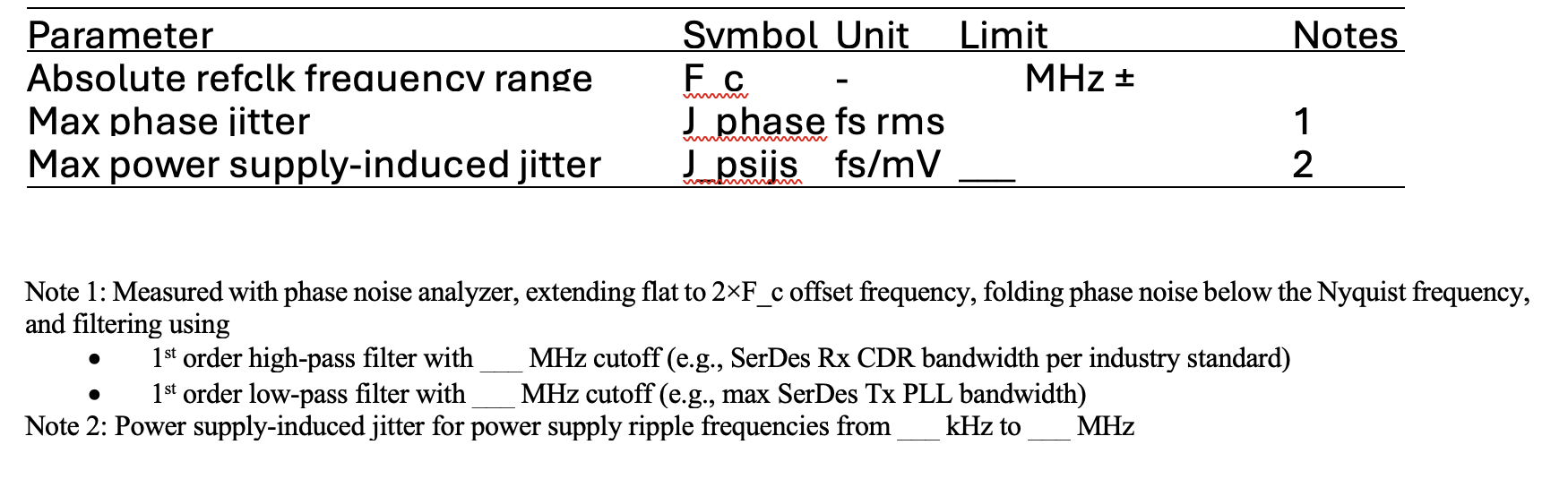
Table 1. Recommended template to specify refclk jitter in SerDes datasheets
By adopting this template, SerDes vendors can better characterize their products and provide customers with the necessary details to select timing devices that optimize system performance—especially in space constrained and noisy environments like optical modules.
Real-World Impact: A Case Study
Figure 1 illustrates how traditional refclk jitter analysis can lead to misleading conclusions. Two devices, A and B, have similar legacy phase jitter values (e.g., 70 fs vs. 50 fs RMS) measured using the outdated 12 kHz to 20 MHz approach. However, when analyzed using the recommended methodology—extending phase noise measurements, applying realistic system filters, and considering aliasing—the results change significantly.
For example, Ethernet standards specify a 4 MHz golden CDR bandwidth, while the SerDes Tx PLL bandwidth varies. Using a worst-case 20 MHz Tx PLL bandwidth, Device A performs the same or better than Device B under the new methodology, despite its worse legacy 12 kHz to 20 MHz jitter spec. This demonstrates how modern analysis leads to better device selection and optimized BER performance.
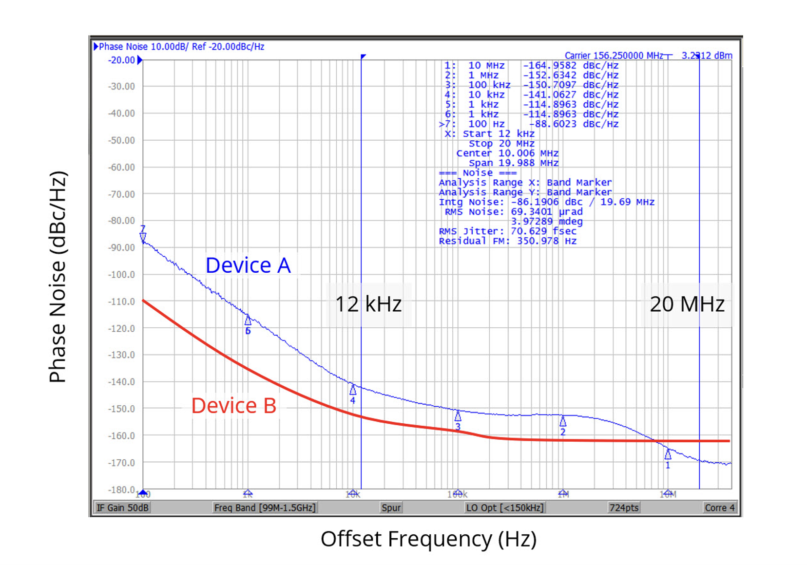
Fig. 1. A traditional refclk jitter analysis estimates devices A and B contribute 70 and 50 fs rms, respectively, at the output of an optical module. Results are for 12 kHz Rx CDR, 20 MHz Tx PLL, no aliasing.
Alternatively, Fig. 2 computes phase jitter for devices A and B per Table 1, Note 1 analysis for Ethernet applications above 10 Gbps.
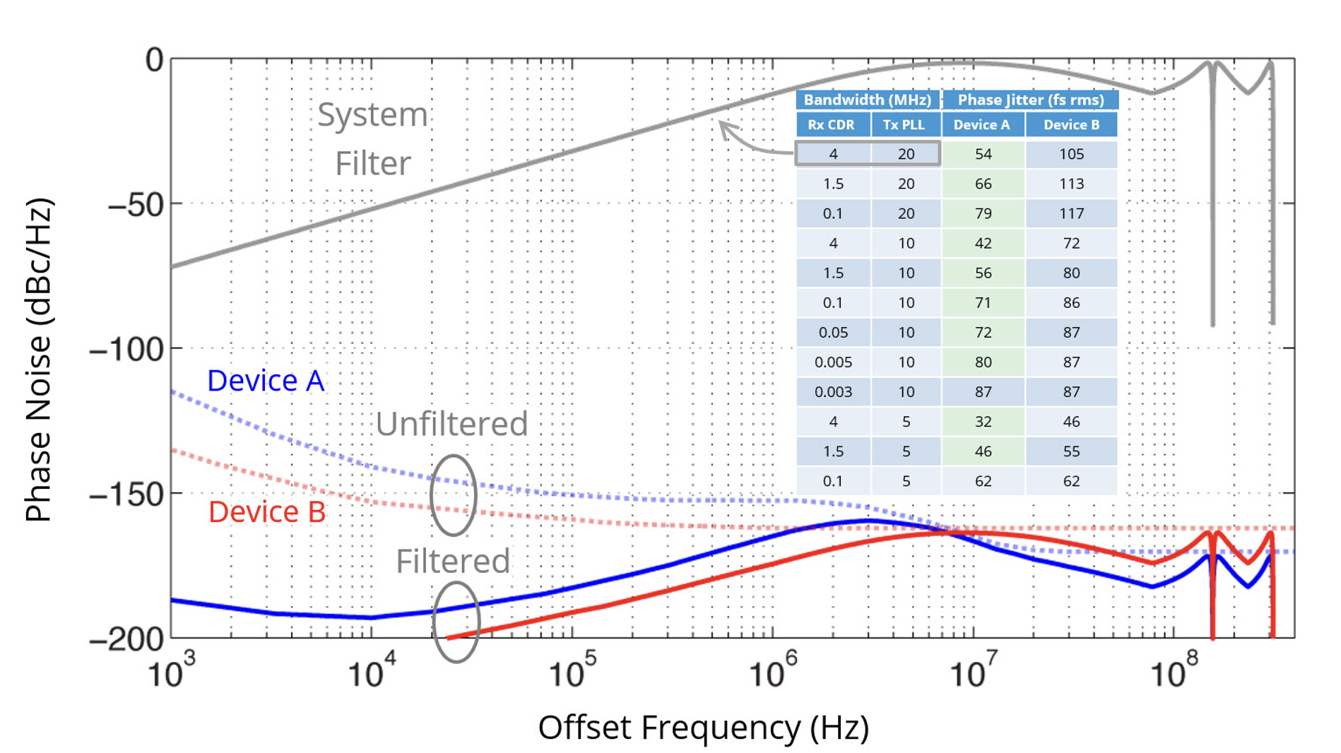
Fig. 2. A more accurate jitter analysis reverses the conclusion of Fig 1, wherein devices A and B are shown to contribute 54 and 105 fs rms phase jitter, respectively, at the output of an optical module. Plots for system filter and filtered data are shown for 4 MHz Rx CDR, 20 MHz Tx PLL, with aliasing.
Here, the last measured phase noise data point is extended flat to 2x156.25 MHz in offset frequency and filtered by a system filter that reflects across Nyquist zones to the same offset frequency (note: this is equivalent to aliasing the extended phase noise curve into the first Nyquist zone before filtering, as described in Table 1, Note 1).
The inset table in Fig. 1 lists computed phase jitter values for a wide range of CDR and Tx PLL bandwidths. Ethernet 10 Gbps and higher specifies a 4 MHz CDR bandwidth, while the Tx PLL bandwidth depends on the SerDes silicon. A worst-case analysis uses a 20 MHz Tx PLL bandwidth. However, different standards require different CDR bandwidths. Nevertheless, Fig. 2 shows in all cases that device A is the same or better than device B using the recommended analysis in Table 1, Note 1. Note how different the new versus legacy analysis results are.
A Better Way to Specify and Analyze Refclk Jitter
The traditional approach to refclk jitter analysis is outdated and no longer useful for high-speed SerDes applications, particularly in optical modules. A new, more precise methodology—already adopted by industry standards—provides a better way to specify and analyze refclk jitter. By adopting this improved approach, vendors and system designers can ensure optimal performance, minimize BER and avoid unnecessary system costs.
For more information:
- How to Evaluate Reference-Clock Phase Noise in High-Speed Serial Links
- Practical Analysis of Refclk Jitter for SerDes Applications Technology Paper