How to Measure Clock Jitter – Part 2
Phase Noise and Phase Jitter
Apr 22-23, 2013
Agenda
- What are phase noise, phase jitter, and TIE jitter?
- Who cares about phase jitter?
- How to measure phase jitter?
What is Clock Jitter
Jitter is, “The deviation of an event timing relative to its ideal value”
- Event? - defined by a specific type of jitter
- Ideal value? - event timing on an ideal clock, often estimated from an average value of the event.
Jitter definitions:
- Period Jitter (Covered in Part 1)
- Deviation of the clock period from averaged value
- Timing Interval Error (TIE) Jitter and Phase jitter (Part 2)
- Error in edge location relative to an ideal clock
- Long Term or Multi-Cycle Jitter (Part 3)
- Deviation of the durations of multiple cycles from the averaged value
- Also known as long term jitter or accumulated jitter
- Cycle-to-Cycle Jitter (Part 3)
- Deviation of the difference of periods of two consecutive clock cycles
What is Phase Noise?
- Noise-free oscillator: Signal energy concentrates in a narrow frequency range (BLUE)
- Real oscillator: Noise spreads the oscillation energy in a larger frequency range (RED)
- Phase noise: The ratio of “noise power spectral density” to the “oscillator carrier power”.
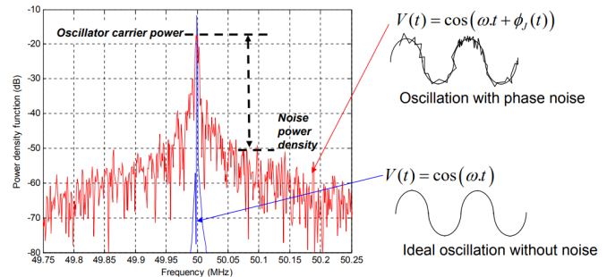
Simulated oscillator spectrum with and without noise
Who Cares About Phase Noise or Phase Jitter?
Digital electronics with high-speed serial I/O:
- System extracts clock signal from serial data transmission
- Common serial I/O standards:
- SAS, SATA, USB for storage device and computer peripherals
- HDMI, SDI for graphics and video equipment
- Ethernet, Fiber-Channel for data communication
- SONET/SDH, DSL, Cable Modem for telecommunication
RF transceivers and frequency synthesizers
- Radio and TV broadcast
- Wireless base stations and handsets
- Wifi, satellite, ……
- Telemetry equipment, GPS
- Instrumentation
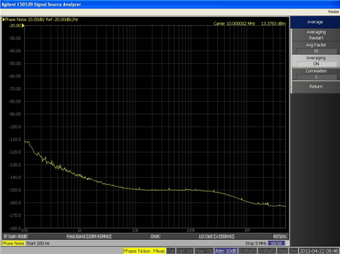
Example: Phase Noise
Phase Noise
- Measure in 1Hz bandwidth
- Expressed in dBc/Hz
- X-axis plotted in frequency relative to carrier → Frequency offset
Phase Jitter Defined
“Phase Jitter” or “Integrated Phase Jitter”
- Phase noise integrated over a specified offset frequency range
- Represents edge location variation relative to an ideal noise-free clock
- Critical specification for serial interfaces (e.g. 1-10GbE, PCIe, SATA/SAS, Fibre Channel, …)
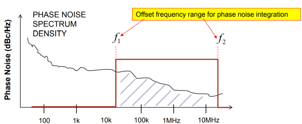
Single-Sideband Frequency Offset from Carrier (Hz)
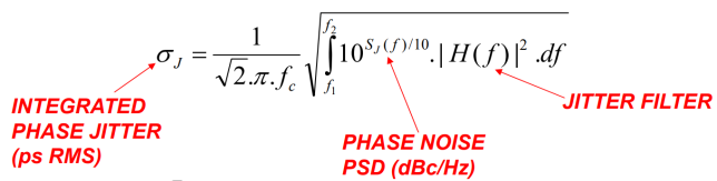
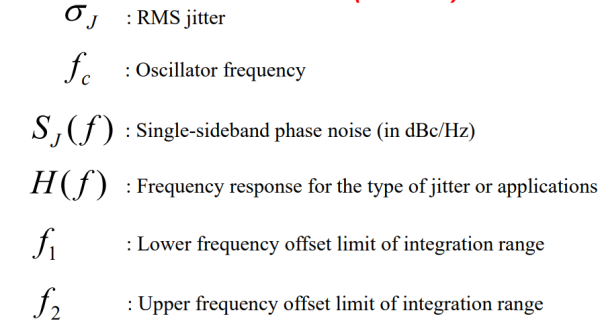
Phase Noise and Phase Jitter
Any type of jitter is related to the phase noise as below:
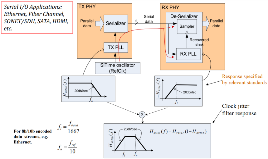
Reference Clock Jitter Filter in Serial I/O Applications
Example: Integrated Phase Jitter
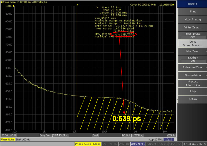
IPJ for SiT8208-50MHz in 12 kHz to 20 MHz range
Example: Integrated Phase Jitter (IPJ) for SATA-1.5Gbps Applications
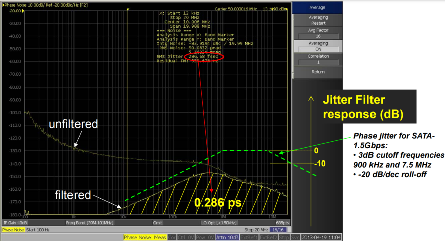
IPJ of SiT8208-50MHz from12 kHz to 20 MHz with SATA jitter filter
Phase Noise Measurement Setup with Phase Noise Analyzer (PNA)
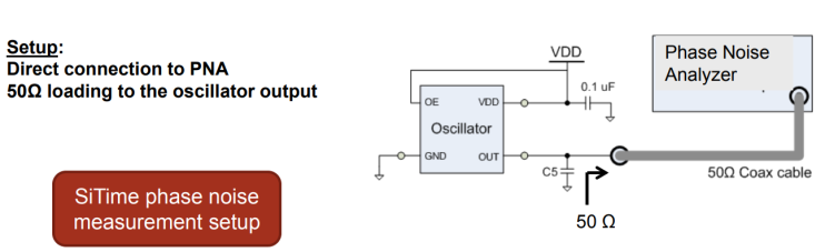
Measure phase noise and phase jitter with PNA:
- Use phase noise analyzer system with low noise floor
- Use clean power supply and power supply bypass for DUT
- Recommended direct 50 Ω connection to PNA
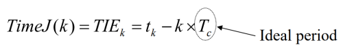
Jitter Definitions and Terminology Time Interval Error (TIE)
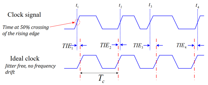
TIE sequence is clock jitter represented in time domain:
Event: rising or falling edge
Ideal value = ideal location in time
- Multiples of ideal period
- Averaged period often used in actual measurement
Jitter Definitions and Terminology Phase Noise and TIE
TIE sequence carries the same information as phase noise in most cases:
- TIE: Discrete-time domain signal
- Phase noise: Continuous-time noise power density in frequency domain
Differences
- TIE is subject to aliasing
- TIE represents the true noise in the signal phase
- TIE is measured with time domain equipment, e.g. real-time oscilloscope
- Phase noise is measured with spectrum analysis equipment, e.g. phase noise analyzer
Both TIE and Phase Noise should be filtered and integrated to obtain “Phase Jitter” relevant to specific applications!
TIE Jitter Measurement Setup with Real-Time Oscilloscope
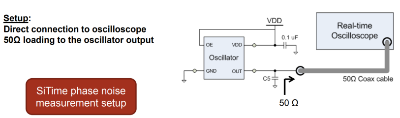
Measure TIE Jitter with Real Time Oscilloscope:
- Use oscilloscope with low time base error (< 0.5 ps rms)
- Optimize oscilloscope settings to reduce measurement error
- Direct 50 Ω connection to oscilloscope can be used
- Real time oscilloscope has higher noise floor due to wider channel bandwidth and aliasing effect
Example: TIE Jitter with Real Time Scope
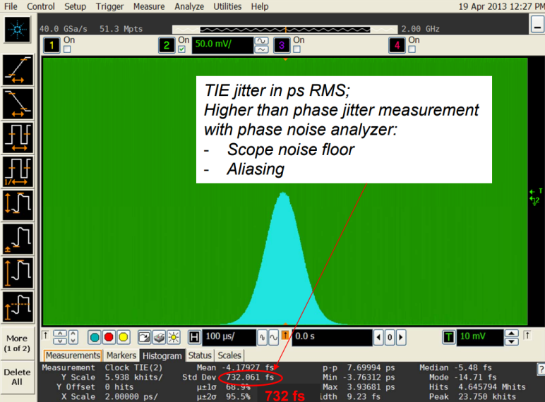
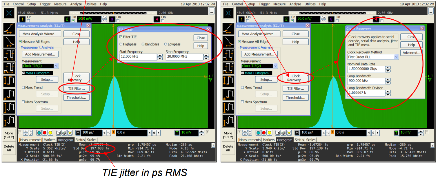
Measure TIE Jitter with Real Time Scope
Measure TIE Jitter with Real Time Scope
Set up “TIE Filter” and “Clock Recovery” for TIE jitter measurement:
- TIE Filter: set the offset frequency range for phase noise integration
- Clock Recovery: set the RX PLL filter corresponding to specific serial interface
Summary
- Phase noise is frequency domain representation of the noise affecting signal phase
- Phase jitter can be measured using phase noise analyzers or scopes
- Understand application requirement for phase jitter measurement:
- Integration bandwidth
- Jitter filter