Every electronic system needs a timing device. And crystal (XTAL) resonators are often the go-to solution. However, oscillators, which pair a resonator with an oscillator IC into one complete integrated timing device, offer several benefits compared to XTALs. These benefits are further extended with MEMS timing technology. System designers no longer need to work around the limitations of XTALs and accept the headaches and risks of designing with crystals.
1. Plug-and-play oscillators simplify system design
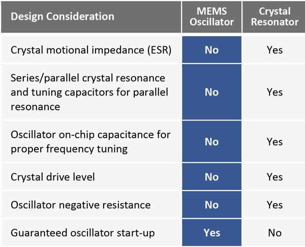
On the surface, oscillator design using quartz crystals might seem straight forward, especially considering the maturity of this technology. But there are a myriad of design parameters to consider when matching a crystal to an oscillator circuit. Among these parameters are crystal motional impedance, resonant mode, drive level, and oscillator negative resistance which is a measure of oscillator gain. Additionally, load capacitance must be considered for parallel resonant mode crystals and it should account for the PCB parasitic capacitance and potentially the on-chip integrated capacitance included in the oscillator circuit.
All of these parameters must be carefully considered to ensure reliable start up and operation of the circuit. Because an oscillator circuit requires close matching of the resonator to the oscillator circuit, crystal vendors cannot guarantee startup of the crystal. By contrast, oscillators are a completely integrated solution. The oscillator manufacturer matches the quartz resonator to the oscillator circuit, thus relieving the board designer of this burden. Because matching errors are eliminated, oscillator start-up is guaranteed by SiTime. In short, oscillators are a plug-and-play solution that greatly simplifies system design.
Design concerns eliminated with MEMS oscillators
Crystal motional impedance and oscillator negative resistance
The oscillator circuit must have enough gain and phase shift to meet the Barkhausen criterion for oscillation. Of particular importance is the motional impedance (ESR) of the crystal and the negative resistance (equivalent to gain) of the oscillator. If the oscillator has insufficient gain to overcome the motional impedance of the quartz resonator, the circuit may not start up. These issues are eliminated with the use of oscillators.
Crystal resonance mode, frequency tuning capacitance, and on-chip oscillator capacitance
Quartz crystals can resonate in either series or parallel resonant mode, but they are typically calibrated for only one of these two modes. If calibrated for parallel resonance, they require a specific load capacitance which is usually specified. However, the proper capacitance is not used, the frequency error may exceed the datasheet specifications. The oscillator IC may or may not have integrated chip capacitance which must be taken into account along with any parasitic capacitance from the printed circuit board connections, bond wires and lead frame of the oscillator IC to ensure the best frequency accuracy.
In contrast, MEMS oscillators integrate the resonator and oscillator/PLL IC into one package, eliminating the need for an external capacitor to tune the resonant frequency.
Crystal drive level
Care must be taken to ensure the oscillator circuit does not overdrive the crystal resonator. Overdriving the resonator can lead to accelerated aging of the crystal resonator and at extreme levels, it can damage the crystal. In contrast, MEMS resonators do not experience aging.
2. MEMS oscillators offer much better quality and reliability
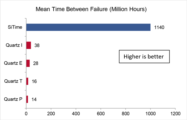
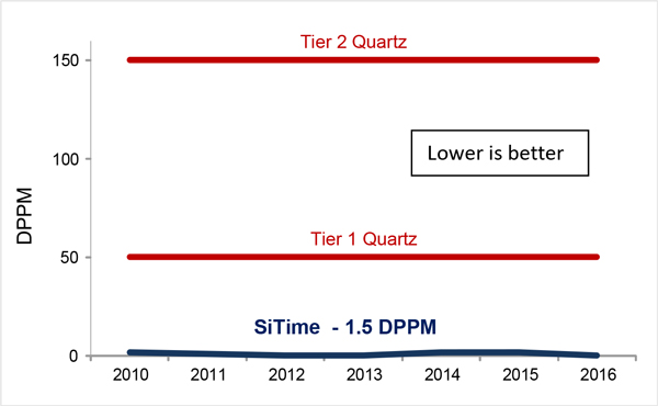
Quality and reliability are critical – not only are company reputations at stake, but re-work can be costly and time consuming. Moreover, systems that are deployed outdoors and exposed to environmental stresses must be especially robust. Quartz resonators, while a mature technology, involve a rather complicated manufacturing process in which each individual resonator is tuned to the desired frequency, usually by ablating the metal electrode with an ion beam. This step occurs before the crystal is encapsulated and causes the resonator to be susceptible to contamination. This process, along with other quartz manufacturing complexities, result in the mean time between failures (MTBF) of quartz to be as low as 14 to 38 million hours. The defective parts per million (DPPM) is up to 50 for the best quartz manufacturers and as high as 150 for tier 2 quartz suppliers.
In contrast to the specialized manufacturing processes of quartz crystals, MEMS oscillator manufacturers use standard semiconductor batch mode techniques. This includes wafer level production of resonators and oscillator ICs, and die bonding to standard lead frames with plastic encapsulation. SiTime MEMS resonator die are made from a single mechanical structure of pure silicon. During the manufacturing of SiTime MEMS, an Epi-Seal process is used to clean the resonator, after which polysilicon is deposited to seal the structure. The ultra-clean hermetic vacuum seal ensures the resonator structure is protected and free of contamination, eliminating aging mechanisms.
As a result, the DPPM and MTBF of SiTime oscillators are about 30 times better than quartz, providing a very reliable technology platform that endures severe environmental stresses and delivers a high quality product for the end user.
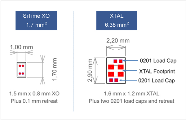
3. MEMS low-frequency oscillators consume 65% less board space
Oscillators are a completely integrated solution and do not require external components such as power supply decoupling caps. SiTime’s 1.5 mm x 0.8 mm (1508) footprint is smaller than the smallest quartz crystal footprint at 1.6 mm x 1.2 mm. And when taking into account load capacitors that are needed for the 32 kHz quartz crystal, the total board area or the XTAL solution is over three times larger.
4. Oscillators can drive multiple loads, reducing costs, BOM and board space
An oscillator is an active circuit with an output driver usually capable of driving 2 to 3 loads depending on the drive strength. This allows the oscillator to replace several crystals and their associated capacitors, further reducing BOM, system cost, and board area.
5. MEMS oscillators are much less sensitive to EMI
Electromagnetic energy, which is common in most systems, can be picked up by exposed PCB traces that connect the crystal resonator to the IC containing the oscillator circuit. This noise can be coupled into the oscillator circuit and passed to the output, potentially adding jitter and noise to the system. However, integrated oscillators have no exposed PCB connections between the resonator and oscillator IC, and the bond wires or balls that connect the MEMS resonator to the IC are extremely short. This makes MEMS oscillators much less sensitive to EMI. As shown in the following table and plot, SiTime oscillators are up to 11.3 dBm less sensitive (134x on a linear scale) than crystal resonators.
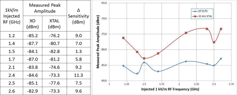
This test was performed per IEC 62132-2 standard that injects electromagnetic energy into a transverse electromagnetic (TEM) cell where the device under test (DUT) is mounted.
6. MEMS oscillators are much less sensitive to vibration
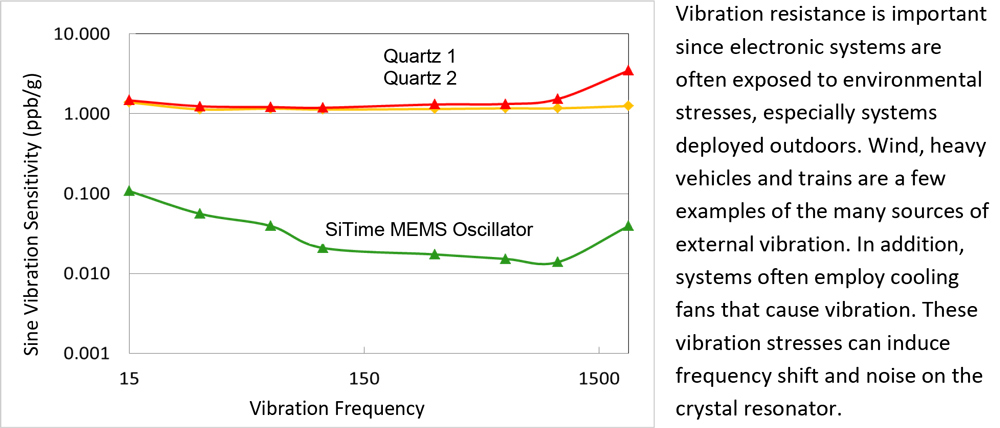
Some systems that require a very stable frequency, such as wireless base stations and small cells, can experience system failure and service interruptions due to vibration.
MEMS oscillators are vibration resistant because the mass of a MEMS resonator is approximately 1,000 to 3,000 times lower than the mass of a quartz resonator. This means a given acceleration imposed on a MEMS structure, such as from shock or vibration, will result in much lower force than its quartz equivalent and therefore induce a much lower frequency shift. The figure on page 5 shows that SiTime MEMS oscillators are more than 10 times lower (better) in vibration sensitivity compared to quartz oscillators. Note this figure is based on measurements of quartz oscillators rather than passive crystal resonators, but comparable results are expected on quartz crystal resonators.
7. MEMS oscillators are readily available in any frequency
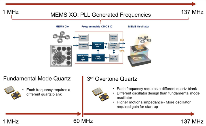
The quartz supply infrastructure has several constraints which can result in long lead-times, on the order of 12 to 16 weeks or even longer. One constraint is the limited number of ceramic package suppliers. Another constraint is the limited availability of frequency options. With quartz products, every frequency needs a different crystal cut unless a programmable phase locked loop (PLL) is used. Therefore, lead-times for non-standard frequencies can be very long.
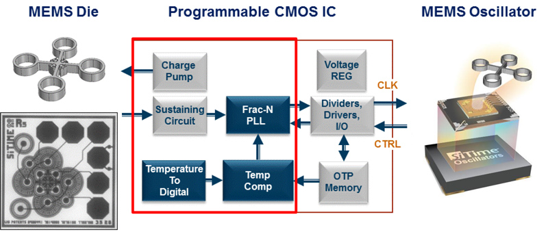
In contrast to crystal resonators, MEMS resonators are based on a standard resonator configuration. The output frequency of MEMS oscillators is generated by programming the PLL to different multiplication values. This enables a very wide frequency range with six digits of accuracy. In addition, silicon MEMS oscillators are manufactured using standard semiconductor processes and packaging. Because MEMS oscillator vendors leverage the very large semiconductor industry infrastructure, capacity is virtually unlimited.
MEMS oscillator samples can be programmed and available within one day, even for non-standard frequencies. By using SiTime’s low-cost Time Machine II programmer and field-programmable oscillators, designers can instantly program oscillators in their lab to create a device with any frequency, any supply voltage and any stability within the device’s operating range. Production lead-times are only 6 to 8 weeks.
8. One qualification for an entire product family
Qualifying components for end-use (system) conditions can consume significant time and resources. However, qualification efforts can be reduced with MEMS oscillators. SiTime products are based on a programmable platform which allows each device within a base product family to generate a wide range of frequencies, supply voltages and stabilities. If for example, resources have been invested in qualifying a SiTime device at a particular output frequency and a new board design requires a different frequency, the existing qualification data may be extended to a part with a new frequency.
In contrast, each XTAL frequency requires a different quartz blank. And if a design requires frequencies above 60 MHz, a different technology other than fundamental mode quartz is often used. Third overtone quartz crystals are often used for higher frequencies. This mode can introduce additional challenges to ensure reliable start up (i.e. higher motional impedance and different oscillator circuit than fundamental mode) which requires qualification.
Summary
Despite inherent limitations, crystals have been the standard in electronic timing for several decades. SiTime’s MEMS oscillators overcome these limitations and offer many benefits compared to traditional quartz crystal resonators. Designers no longer need to accept the headaches and limitations associated with XTALs.
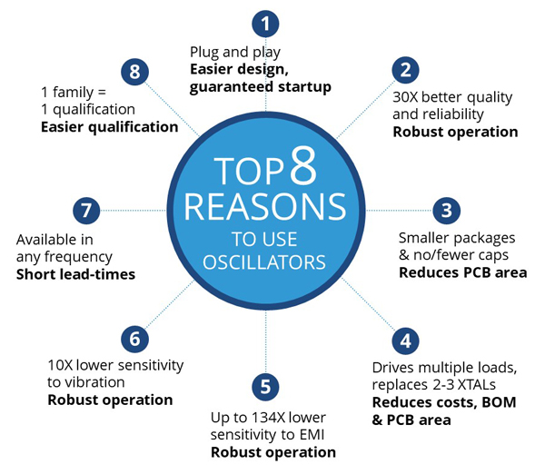
The top 8 reasons to replace XTALs with MEMS oscillators are:
- Oscillators are “plug and play” – much easier to design, guaranteed startup
- 30X better quality and reliability – lowers cost, increases robustness
- Smaller package and no/fewer caps – reduces PCB area
- Drives multiple loads, replacing 2 to 3 quartz crystals – reduces costs, BOM and PCB area
- Up to 134X lower sensitivity to electromagnetic energy – more robust
- 10X lower sensitivity to vibration – more robust
- Available in any frequency – very short lead-times
- One MEMS product covers a large frequency range – reduced qualification effort