A MEMS TCXO with Sub-ppm Stability
Aaron Partridge, Hae-Chang Lee, Paul Hagelin, Vinod Menon SiTime Corp, USA
Abstract
This paper introduces a MEMS-based TCXO that delivers <1ppm (parts per million) frequency stability from -40C to +85C. Its system architecture, MEMS resonator, and key circuit blocks are described. The oscillator achieves a phase noise of -134dBc/Hz at 1kHz and -142dBc/Hz at 10kHz from a 26MHz carrier, with a far phase noise of -158dBc/Hz. Moreover, its integrated jitter is 0.5ps from 12kHz to 20Mhz. The oscillator’s frequency is programmable from 1MHz to 220MHz and it draws 32mA from 1.8V to 3.3V supply at 26MHz. The transition from quartz- to MEMS-based oscillators is also discussed, with a review of the oscillator architecture and accompanying benefits, e.g. programmability, improved reliability and robustness, and decreased sensitivity to vibration and EMI.
1. Introduction
MEMS oscillators are displacing quartz oscillators in clocking, timing, and frequency generator applications. In this paper, we discuss the first commercial MEMS oscillators that are stable to better than one part per million (ppm). The focus of this paper is on architecture of these oscillators and how this architecture is improved from that used in the legacy quartz oscillators.
In all commercial MEMS oscillators, the output is derived from a MEMS resonator where the resonator’s frequency is translated with a frac-N PLL. Under control of a digital state machine, the PLL compensates for the resonator’s initial frequency offset and frequency variation over temperature. Quartz oscillators usually produce an output frequency at their crystal’s resonance, and do not rely on circuitry to adjust that frequency. In temperature compensated quartz oscillators, the frequency compensation is usually provided by pulling the resonator through capacitive loading, not with a fractional PLL.
MEMS oscillators are thus circuit-centric, whereas simple quartz oscillators are material-centric. This choice of circuit-centric approach is driven by the needs of the MEMS resonators and by market requirements, and is made possible by the advancing capabilities of CMOS.
MEMS and quartz oscillators can be divided into three categories: XOs, that provide accuracies of ±100ppm (parts per million) to ±25ppm. Temperature compensated oscillators, TCXOs, that provide accuracies of ±2.5ppm to ±500ppb (parts per billion), and in rare cases to ±100ppb. And ovenized oscillators, OCXOs, that provide accuracies from ±100ppb down to ±1ppb or lower. Their prices vary inversely with their accuracy; a 50ppm oscillator may cost $0.40 while a 1ppb oscillator may cost $400.
2. Architecture
There are three application drivers that quartz addresses with mechanical processes that MEMS addresses electronically: (1) providing a wide range of application frequencies, (2) trimming the resonator frequency over production tolerances, and (3) compensating the resonator frequency over temperature.
Commercial applications specify hundreds of different frequencies. In quartz oscillators, the resonators must be manufactured precisely to these frequencies, necessitating the crystals to be cut and ground to hundreds of different thicknesses. Second order effects often require the lateral dimensions of the crystals to be optimized for each frequency.
Building MEMS resonators across widely varying frequencies would be difficult, time consuming and expensive. Commercial MEMS resonators required years of individual development, usually involving many fab-and-test cycles. Deriving designs with different frequencies is generally not straightforward. For resonators with lateral modes, the dimensions or shapes are specific for each frequency, and this implies additional tape-outs, one for each frequency. For resonators with vertical modes, multiple material thicknesses would need to be optimized for each frequency. Clearly for MEMS resonators, supplying hundreds or even dozens of frequencies could be commercially unviable.
Quartz crystals are individually trimmed to their specified frequencies, or in the case of TCXOs are trimmed to within the pull range of their specified frequencies. This mechanical trimming is usually done by ion milling or laser ablating the quartz or metallization. MEMS resonators can also be trimmed this way; however mechanical trimming can complicate the already difficult MEMS design and packaging.
Present-generation MEMS resonators show greater temperature sensitivity than AT-cut quartz, and while MEMS can be temperature compensated [1] the devices shown to-date have greater sensitivity than can be tolerated by many applications. For this reason MEMS oscillators are generally electronically temperature compensated. In this sense, they are like quartz TCXOs. But unlike quartz oscillators that are temperature compensated only for certain precision applications, MEMS oscillators are compensated for the majority of applications. Unlike quartz TCXOs, MEMS oscillators are generally not trimmed by resonator pulling, but instead with fraction PLL multiplication.
Fractional PLL technology was not available for early quartz oscillators. The designers therefore had no alternative other than to develop a resonator technology that could support a range of frequencies, could be trimmed, and in some cases adjusted or pulled over temperature. On the other hand, we now have the circuit technology to program MEMS oscillator frequencies to their application requirements, trim them over production, and compensate them over temperature.
Using this circuit-centric approach simplifies the MEMS resonator development and production while also providing significant commercial benefits. For instance, inventories of oscillators with various pre-defined frequencies are not needed, and custom frequencies can be supplied quickly.
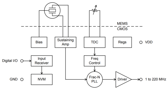
Figure 1. Oscillator topology
Figure 1 shows the circuit-centric oscillator topology. The architecture includes a PLL to translate the resonator frequency to the application requirements. The PLL is fractional in order to trim the resonator across production tolerances, and its multiplication value is variable in order to compensate for temperature. A state machine (in hardware or software) controls the PLL, and draws its parameters from non-volatile memory.
Since this architecture works well for MEMS oscillators then why is it not used for quartz too? Or in other words, why not apply this new circuit technology back to quartz oscillators? We have not seen this to any significant extent. There are likely many reasons, among them is that the incumbent industry has organizational inertia – most of the quartz suppliers are expert at crystal machining but not at circuit design. Developing a circuit infrastructure would be slow and expensive for them.
2. Key Circuits
The TDC (Temperature to Digital Converter) provides the temperature compensation data. The TDC in the oscillator detailed here is optimized for low temperature readout noise because noise in the temperature data becomes near phase noise in the output frequency. For this oscillator’s target applications we require phase noise levels that necessitate particular attention to the TDC.
One has many options when designing temperature sensors. The default topology is a Delta-VBE circuit using bipolar transistors in the CMOS die. These temperature sensors have many favorable characteristics: they are linear, easy to calibrate, well understood, highly evolved, use moderate die area, and are low power. In addition they are purely circuit-based.
However, in this case we have chosen to use thermistors as the detection elements because thermistors offer higher signal to noise.
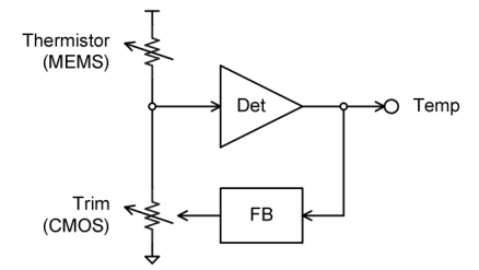
Fig.2. Balanced Bridge TDC
Figure 2 shows the balanced bridge topology we use to digitize the thermistor resistance. The feedback loop works to keep the node between the Thermistor and the Trim reference resistor at mid value, the Temp output is a digital value.
To build this TDC one must have a stable reference resistance, but such a resistance is not available in common CMOS. We therefore construct an equivalent reference with a switched capacitor. Capacitors are inherently stable in CMOS and we have a stable reference frequency derived from the MEMS resonator to time the capacitor switching. The resonator frequency does change as a function of temperature, but two orders of magnitude less than the thermistor resistance, and also in a predictable manner, therefore it can be considered a fixed frequency. The resulting reference is thus highly stable.
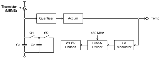
Figure 3. Switched cap reference resistance
Figure 3 shows further detail of the TDC converter. The TDC works by forcing the effective resistance of the switched capacitor to match the thermistor resistance. By closing Ø1 then Ø2 at a selectable rate, the switched reference capacitor C2 obeys Ohm’s law with a selectable resistance. The rate is controlled by a sigma-delta feedback loop driving a fractionally derived frequency. Capacitor C1 averages current across the switching. In this way, the loop balances the Thermistor resistance and provides the digitized Temp output. The majority of the loop is digital, starting at the Quantizer.
The TDC is more complex than what is described here in three ways: (1) the Thermistor is measured differentially with its polarity swapped and sensed by two sets of circuits, (2) the Thermistor is driven and sensed in a four-wire configuration with Kelvin connections, and (3) the implied mid-supply reference in the Quantizer is developed dynamically. A more detailed description of the TDC is published by M. Perrott [2].
that there is never a voltage or current from the Thermistor to an ADC. The Thermistor and TDC work in a feedback system to derive the temperature, there is never an analog temperature value that is digitized.
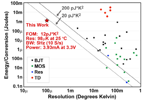
Figure 4. Figure of merit comparing conversion energy and resolution
The TDC delivers a resolution of 98uK at 5Hz bandwidth while consuming 3.9mA at 3.3V. Figure 4 compares its energy efficiency and resolution against other integrated TDCs. This TDC provides over an order of magnitude lower noise than others in the comparison population and does so at under 20pJK2 . The comparison data in this plot is compiled by K. Makinwa [3].
The frac-N PLL provides an output frequency programmable from 1MHz to 220MHz (after a final divide by 2). It is optimized for low phase noise and low power. Figure 5 shows its block diagram. Details of the PLL have been published by F. Lee [4].
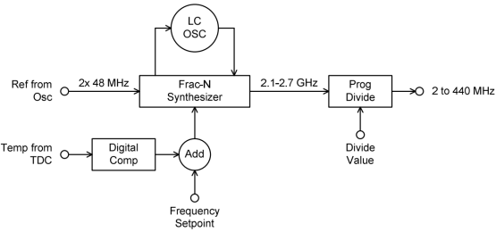
Figure 5. Frac-N PLL
A PLL normally is thought of as a frequency translation circuit, and for that function it consumes power. It is sometimes thought that this is a “waste” of power because if the resonator had been at the output frequency the PLL would not be needed. However, a key benefit of the PLL is that above its filter bandwidth it provides lower phase noise that its reference.
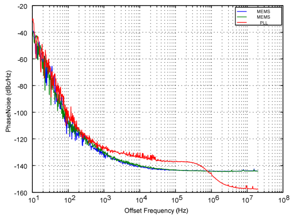
Figure 6. MEMS and PLL phase noise, reference frequency is 48MHz
Figure 6 shows the phase noise of the MEMS output and the PLL output. The PLL output phase noise is 6dB higher than the MEMS reference from 10kHz to 300KHz, but its far phase noise is 12dB lower. The far phase noise often matters more than the near phase noise. For instance in high speed serial links, the key specification is integrated jitter from 12kHz to 20MHz. The integration is linear across frequency, so the far phase noise dominates the near phase noise. The integrated jitter after the PLL is lower than before it.
For high speed serial links, at the common output frequency of 156.25MHz, the oscillator show a 12kHz to 20MHz integrated phase jitter of 0.5ps, which quartz suppliers consider extremely low jitter. Thus we say, “PLLs are our friends!” They do more than just frequency translation, trimming, and compensation. They decrease the output phase noise.
3. MEMS resonators and thermistors
Development of MEMS resonators dates to the late-1960, with the first published results by Nathanson 1967 [5]. The early resonators were audio filters, and were not suitable for references. As references, they would not have provided the required stability or phase noise. Their limits can be traced to the resonator material and the packaging cleanliness.
In order for a resonator to have a stable frequency, one must build it from a stable material. The first resonators were built from metal, but were not sufficiently stable for frequency references as metal is subject to internal stresses, hysteresis, and aging. Material advances in the late 1970’s at IBM [6,7] and Berkeley in the 1990’s showed silicon oxide and polysilicon respectively [8] as resonator materials. Further work in the 1990’s and early 2000’s developed single crystal silicon as an optimal resonator material. Presently both single crystal and polycrystalline silicon are used in MEMS resonators. Other siliconcentric materials, including Aluminum Nitride are in development, some for many years [9]. But to date none except silicon has seen commercial success. Research on more exotic materials such as polycrystalline diamond is underway [10,11].
As resonators are reduced in size their volume to surface ratio decreases, consequentially their sensitivity to surface contamination increases. To maintain stabilities in the parts-per-million range expected of frequency references, one must minimize mass-loading the resonators with contamination. One finds that even a monolayer of surface contamination can shift a resonator’s frequency out of specification. This drives a requirement for very clean packaging. Bonded covers have been made sufficiently clean to produce commercial resonators with XO-type accuracy. The epitaxially encapsulation used in the parts described here is likely cleaner and readily enabled TCXO to OCXO-level stability.
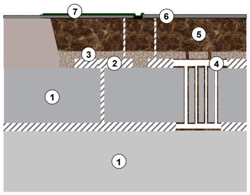
Figure 7. MEMS encapsulation cross section
Figure 7 shows a cross-section diagram of the encapsulation used for the resonator and thermistor. This encapsulation is built as follows: (1) an SOI wafer is trenched to define the resonator, (2) protective oxide is deposited and patterned, (3) silicon is deposited and patterned with vents, (4) the resonator is released, (5) the vents are closed and thick encapsulation is deposited, (6) contact isolation trenches are etched and oxide filled, and (7) metal traces are fabricated and passivized in the normal way.
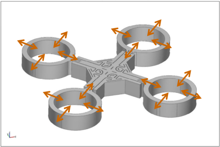
Figure 8. Resonator isometric view
Figure 8 shows an isometric view of a 48MHz resonator. The arrows indicate the mechanical motion in resonance with each ring expanding and contracting in phase. There are electrostatic drive and sense electrodes inside and outside of each ring. The rings are anchored proximal to the midpoint of the cross beams.
Figure 9 shows a network analyzer plot of a nominal resonator response. The resonant frequency is 48.016MHz, and the quality factor is 147k.
Figure 10 shows an example SEM cross section in this process. The SEM is taken of an edge of a wafer that has been cleaved and from which a resonator is protruding. The top of the SEM shows the top surface of the MEMS wafer.
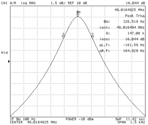
Figure 9. Example resonator response, f = 48.016 MHz, Q = 147k
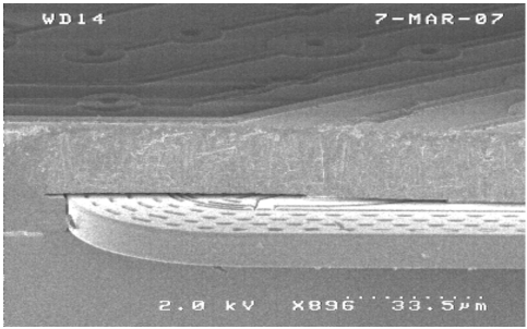
Figure 10. Resonator cross section SEM of cleaved wafer
The MEMS thermistor is built in single-crystal silicon. Like the resonator it is fully vacuum encapsulated and released. Because it is encapsulated with the resonator, it is protected from environmental contamination and therefore highly stable. The resistor is released from the substrate.
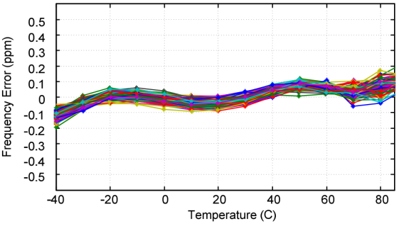
Figure 11. Compensated output frequency v. temperature
Output phase noise is a function of the output frequency. Figure 12 shows the phase noise at 156.25MHz, a common frequency for high speed serial link systems.
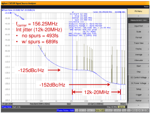
Figure 12. Output phase noise at 156.25 MHz. Measured on Agilent 5052B
The integrated phase noise from 12KHz to 20MHz in this case is 493fs not including spurs and 689fs including spurs. Generally the telecom application at this frequency accounts for spurs elsewhere and cares about the random integrated jitter, which is the 493fs value.
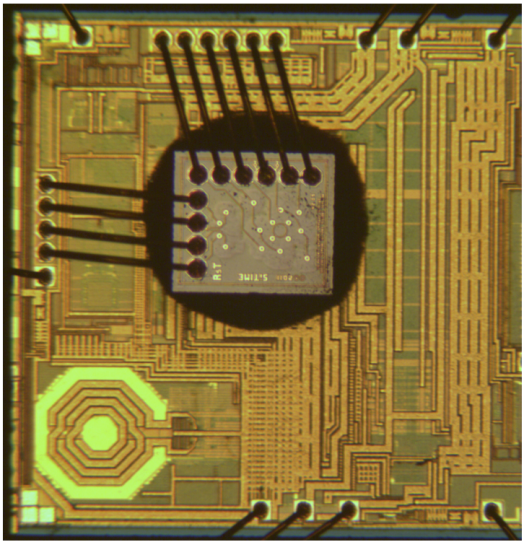
Figure 13. Die photo
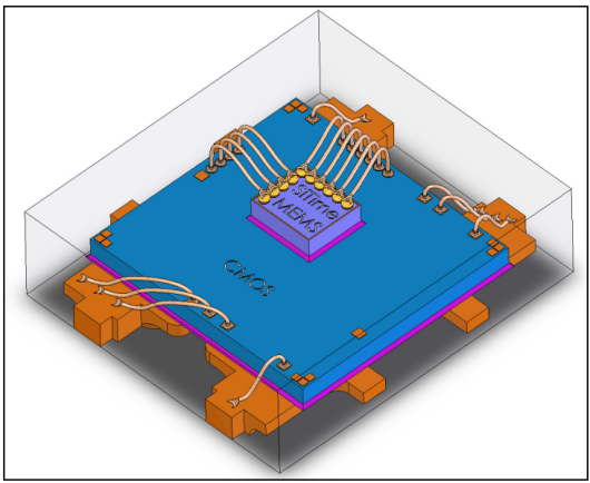
Figure 14. Package diagram showing leadframe, CMOS, and MEMS die
Figure 13 shows the die photo, and Figure 14 shows a diagram of the packaged MEMS and CMOS die. The MEMS die is mounted on top of the CMOS die which is molded into a QFN package.
5. Looking Toward TCOCXOs
When an oscillator is maintained at an elevated temperature it delivers better frequency stability than when its temperature is allowed to vary with the ambient. When a TCXO is ovenized it is called an OCTCXO.
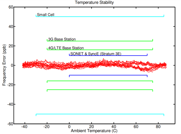
Figure 15. Oven controlled output frequency vs. ambient temperature
Figure 15 shows the frequency vs. temperature of the MEMS oscillators built into an oven module. When operated as OCTCXOs their frequency can be stabilized to ±10ppb over -45C to +90C. The brackets in Figure 15 show common application temperature and accuracy requirements, including cell base stations and Stratum-3E oscillators for telecom networking. Accuracies from 10ppb to 100ppb are normally provided by quartz OXCOs today, although most quartz OCXOs do not operate over the full -40 to +85C temperature range.
Note that the results shown in this paper are from production material, except for the data in Figure 15 which is from a single part on a bench. Nonetheless, it is important to understand that MEMS oscillators will likely support these OCXO applications.
6. Conclusions
Looking forward, it is likely that this circuit-centric architecture will dominate timing generation. The advantages over the simple oscillator architecture are profound and the costs, in terms of both power and die area, are steadily decreasing.
Presently almost 200 million MEMS oscillators have been produced with this circuit-centric architecture. The growth rate of this segment is strong, at about 70% per year. SiTime has been listed by Deloitte LLP in their Fast 500TM rankings as the fastest growing semiconductor company in North America [12]. The same is not true for the quartz suppliers, for whom growth is modest to negative. There are many reasons for this shift, among them are that MEMS shows better reliability, robustness, supply chain support, and cost structure that quartz. And a significant reason is that the MEMS oscillators are based on a programmable, flexible, and highly accurate, modern architecture.
References
[1] R. Melamud, B. Kim, S.A. Chandorkar, M.A. Hopcroft, M. Agarwal, C.M. Jha, T.W. Kenny, “Temperature-compensated high-stability silicon resonators,” Appl. Phys. Lett. p.90, 2007.
[2] M. Perrott, J.C. Salvia, F.S. Lee, A. Partridge, S. Mukherjee, C. Arft, J. Jim, N. Arumugam, P. Gupta, S. Tabatabaei, S. Pamarti, H.C. Lee, F. Assaderaghi, “A temperature-to-digital converter for a MEMS-based programmable oscillator with frequency stability and <1ps integrated jitter”, IEEE J. of Solid-State Circuits, v.48, i.1, pp.276-291, 2013.
[3] K.A.A. Makinwa, “Smart Temperature Sensor Survey”, http://ei.ewi.tudelft.nl/docs/TSensor_survey.xls.
[4] F.S. Lee, J. Salvia, C. Lee, S. Mukherjee, R. Melamud, N. Arumugam, S. Pamarti, C. Arft, P. Gupta, S. Tabatabaei, B. Garlepp, H.-C. Lee, A. Partridge, M. Perrott, and F. Assaderaghi, “A programmable MEMSbased clock generator with sub-ps jitter performance,” in Proc. Symp. VLSI Circuits, pp. 158–159, 2011.
[5] H.C. Nathanson, W.E. Newell, R.A. Wickstrom, J.R. Davis Jr., “The Resonant Gate Transistor,” IEEE Trans. Electron Devices, Vol.ED14, pp.117133, 1967.
[6] K.E. Petersen, “Silicon as a mechanical material,” Proc of the IEEE, v.70, n.5, pp.420-457, 1982.
[7] K.E. Petersen, private communication.
[8] C.T.-C Nguyen, R.T. Howe, “An Integrated CMOS Micromechanical Resonator high-Q oscillator,” IEEE J. of Solid-State Circuits, v.34, n.4, pp.440-445, 1999.
[9] R. Ruby, P. Merchant, “Micromachined thin film bulk acoustic resonators,” Proc. 1994 IEEE Int. Frequency Control Sym., pp.135-138, 1994.
[10] J. Wang, J. E. Butler, T. Feygelson, and C. T.-C. Nguyen, “1.51-GHz polydiamond micromechanical disk resonator with impedance mismatched isolating support,” Proceedings, 17th Int. IEEE Micro Electro Mechanical Systems Conf., Maastricht, The Netherlands, Jan. 25-29, pp. 641-644, 2004.
[11] T. beyazoglu, L. Wu, A. Lingqi, M. Akgul, Z. Ren, T. Rocheleau, O. Tristan, “2.98-GHz CVD diamond ring resonator with Q>40,000,” Proc. IEEE International Frequency Control Symposium (IFCS), p.1-6, 2012.
[12] Deloitte LLP, “Deloitte’s 2012 Technology Fast 500TM Ranking,” http://www.deloitte.com/assets/DcomUnitedStates/Local%20Assets/Documents/TMT_us_tmt/us_tmt_fast500_ rankings_020713.pdf