Contents
2. Making Precise Current Measurements
4. Making Precise Frequency Measurements
4.1 Frequency Counter Characteristics
4.2 Oscillator Intrinsic Long Term Jitter (LTJ)
4.3 Configuring the Frequency Counter
1 Introduction
SiTime’s TempFlat™ MEMS 32.768 kHz SiT153x/4x oscillators and SiT152x temperature compensated oscillators (TCXOs) are a low-power, cost-effective and reliable alternative to quartz resonator-based solutions used in the multitude of electronic devices that require a timekeeping function. Due to the low frequency and low power drive characteristics of SiT15xx oscillators, certain measurement techniques must be followed to accurately measure three key parameters: device current consumption, output waveform, and frequency. This document describes how to accurately make these measurements.
2 Making Precise Current Measurements
Typical no load operating supply current of a SiT15xx device is in the range 850 nA to 1.3 μA at room temperature depending on the voltage swing of the output stage. When measuring the operating supply current, additional current will come from the load capacitance on the output stage. Because of internal regulation, Vdd supply voltage has very little impact on overall supply current. When measuring supply current down to the nano-amp range, a high-resolution digital ammeter similar to an Agilent 34401A must be used. Typical portable digital multi-meters (DMMs) will not accurately measure current in the nano-amp range. Figure 1 below shows how to hook up a high-resolution DMM when measuring operating current of a SiT153x/4x oscillator.
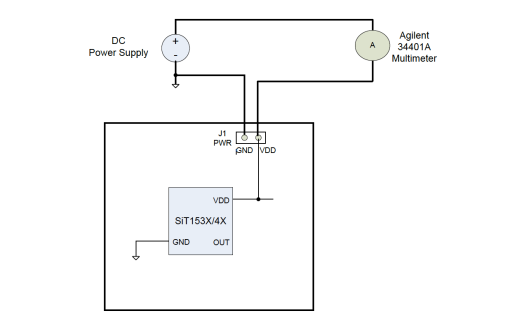
Figure 1: Power supply setup of a high-resolution multi-meter in line with the Vdd rail.
3 Measuring Output Waveform
The SiT15xx output driver is optimized for very low-power applications and is not designed to drive 50-ohm load termination of measuring instrument. To capture the native waveform without loading effects, SiTime recommends using one of the two options listed below:
1. Observe the output waveform via a high-input impedance unity gain amplifier, similar to ADA4817-1 in to a 50 ohm terminated scope.
![Figure 2: A NanoDrive™ waveform captured via a unit gain buffer on a Tektronix TDS 5054 scope. For information on NanoDrive, refer to application note AN10037 [1].](/sites/default/files/resize/inline-images/Figure-2-NanoDrive-Waveform-Captured-Unit-Gain-Buffer-661x297.png)
Figure 2: A NanoDrive™ waveform captured via a unit gain buffer on a Tektronix TDS 5054 scope. For information on NanoDrive, refer to application note AN10037 [1].
2. Use a high impedance probe (> 1 M parallel < 2 pF) similar to a Tektronix P5050 shown in Figure 3.
![Figure 3: Probing a SiT154x output with a high impedance Tektronix Probe P5050. For information on probing, refer to application note AN10028 [2].](/sites/default/files/resize/inline-images/Figure-3-Probing-SiT154x-Output-798x272.png)
Figure 3: Probing a SiT154x output with a high impedance Tektronix Probe P5050. For information on probing, refer to application note AN10028 [2].
4 Making Precise Frequency Measurements
Accuracy and repeatability of frequency measurements of low-power low-frequency oscillators are dictated by two factors:
Frequency counter characteristics The intrinsic long-term jitter (LTJ) of the oscillator
4.1 Frequency Counter Characteristics
The two main characteristics of a frequency or time interval measuring instrument [3] that can adversely impact frequency accuracy are:
- Time base reference frequency stability (ppb)
- Time stamping error
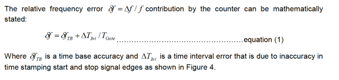
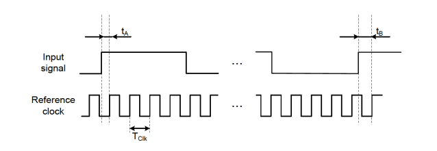
Figure 4: Reciprocal frequency measurement with time stamping capability of modern day frequency counters.
The term represents relative error due to time stamping inaccuracy. The error is constant across the wide range of input signal frequencies, but it increases as gate time gets shorter.
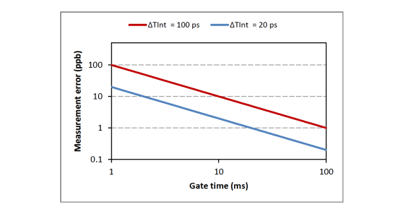
Figure 5: Frequency measurement error (ppb) versus gate time. Two time interval measurement accuracies represent different frequency counters. The plot assumes perfect time base.
Figure 5 illustrates how frequency measurement error changes with gate time for two frequency counters with different time interval measurement accuracy. The time base error is not taken into account in this figure and will add an offset to the plot.
4.2 Oscillator Intrinsic Long Term Jitter
Some micro power 32 kHz oscillators such as SiT15xx devices have relatively higher LTJ. From Equation 1, LTJ adds to the time interval stamping error adversely impacting the measurement accuracy. At gate times greater than 100 ms, the impact of LTJ is averaged out and has minimal impact on the measurement error. To mitigate the impact of LTJ, use a frequency counter such as an Agilent 5313x or 5323x counter that performs additional time interval measurements on several signal edges within the gate time. This class of counters can more accurately measure the native frequency of SiT15xx oscillators at gate times of 100 ms and higher.
4.3 Configuring the Frequency Counter
To perform precise frequency measurements, the frequency counter needs to receive the native clock signal without any amplitude or phase distortion. An incorrectly configured setup may adversely impact the performance of a high resolution frequency counter even though it may run off a Rubidium or GPS time base reference [4][5]. The following setup guidelines must be followed to ensure accurate and repeatable results:
- Input channel frequency response
- AC coupling attenuates lower frequency components
- Use DC coupling
- Input channel impedance
- SiT15xx oscillators can be severely attenuated under a 50Ω load
- Switch to 1 MΩ input termination
- Input trigger sensitivity
- Lower slew rates of SiT15xx devices may cause spurious triggering
- Turn-off auto triggering
- Reduce trigger sensitivity
|
SiTime recommends GPS-disciplined or Rubidium time base for the most accurate measurements and results correlation. SiTime recommends using 100 ms or higher gate time with Agilent 53131/2A and Agilent 53230A frequency counters. For other instruments, like time interval analyzers or simple counters, a gate time of 1 sec or higher is recommended.
5 References[1] SiTime Corp. Application Note AN10037, “Optimized SiT15xx Drive Settings for 32 kHz Crystal Inputs of Low Power MCUs” (http://www.sitime.com/support2/documents/Optimized-SiT15xx-Drive-Settings-for-32-kHz-Inputs-of-Low-Power-MCUs.pdf) (2014). [2] SiTime Corp. Application Note AN10028, “Probing Oscillator Output” (https://www.sitime.com/support/resource-library/application-notes/an10028-probing-oscillator-output) (2013). [3] Agilent Technologies. Application Note 200, “Fundamentals of the Electronic Counters” (http://cp.literature.agilent.com/litweb/pdf/5965-7660E.pdf) (1997). [4] Agilent Technologies. Product Datasheet 5990-6283EN, “Agilent 53131A/132A/181A Counters” (http://cp.literature.agilent.com/litweb/pdf/5967-6039EN.pdf) (2011). [5] Agilent Technologies. Application Note, “10 Hints for Getting the Most from Your Frequency Counter” (http://cp.literature.agilent.com/litweb/pdf/5989-8431EN.pdf) (2008). |