Content
2. Testing Susceptibility to EMI
4. Oscillators Design to Reduce EMI Sensitivity
1 Introduction
Power supplies, power lines, lightning, computer equipment, and electronic components are all potential sources of electromagnetic interference (EMI) that may affect the performance of electronic components. EMI can be conducted from one component to another via electrical pathways in a single system or be transmitted through airwaves. Devices that need to communicate via RF intentionally emit electromagnetic signals that can interfere with other equipment, but even devices that are not designed to emit electromagnetic signals may unintentionally contribute to EMI noise. FCC regulations limit allowed emissions from certain classes of devices, such as computing equipment and microwave ovens, but this does not guarantee that electronic components will not be damaged by EMI from consumer products. Nearly every electronic device or component is capable of generating EMI, and it is important to consider EMI exposure as part of circuit design because of the damage it can do to electronic components including timing devices.
Phase noise and phase jitter of oscillators may increase substantially in the presence of external sources of EMI. It is possible to reduce EMI reaching the oscillator through board-level shielding or filtering, but this approach is not always successful. By evaluating the electromagnetic susceptibility (EMS) of various oscillators, we can determine factors that contribute to EMS and understand how proper oscillator design can minimize detrimental effects of EMI on clock performance.
2 Testing Susceptibility to EMI
Since radiated EM noise adversely impacts the phase noise performance of oscillators [1] [2], the test methodology involved subjecting each device under test (DUT) to a fixed power of radiated EMI and measuring incremental phase noise spur power at the correlated offset frequency. Figure 1 shows the phase noise plots of a 26 MHz quartz oscillator when not exposed to EMI and when subjected to EMI noise at carrier frequency of 80 MHz. The phase noise spur at the 2 MHz offset of the oscillator output frequency can be derived from the aliased frequency formula shown below:
Falias = Femi – N*Fc …………………………….. Equation 1
Femi = Frequency of the injected EMI noise; Fc = oscillator nominal clock frequency; N is a positive integer > 1.
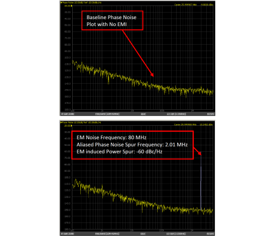
Figure 1: Phase noise of a 26 MHz quartz oscillator without and with EMI noise injection
SiTime used an accredited test lab to perform EMS tests according to the electromagnetic compatibility standard IEC 61000-4.3 [3] across several quartz and MEMS based oscillators. Both single-ended and differential-ended oscillators as listed in Table 1, were tested. The IEC 6100-4.3 standard specifies an induced electromagnetic field with strength of 3V/m at the DUT and a carrier frequency sweep from 80 MHz to 1 GHz in steps of 1%. The test is conducted in an anechoic chamber using the setup shown in Figure 2. The device under test is positioned so that it is aligned with the axis of the vertically polarized antenna, as shown in Figure 3.
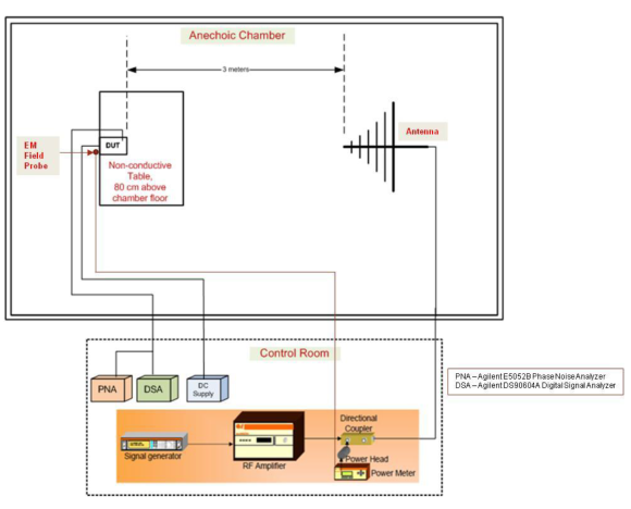
Figure 2: Setup for EMS Testing
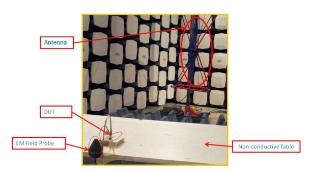
Figure 3: Photo showing the antenna and testing table inside the anechoic chamber
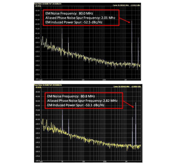
Figure 4: Noise spur test results for noise generated for 3V/m EM field at 80 and 80.8 MHz in an anechoic chamber for a quartz device
The phase noise analyzer captures phase jitter and phase noise for each device under test. Under the influence of the induced EM field, the phase noise plot will show more pronounced spurious noise, or phase spurs, at a frequency aliased to that of the EM interference, as shown in Figure 4. High amplitude phase noise spurs, on the order of -50 dBc/Hz for a quartz oscillator shown in Figure 4, are concentrated at the aliased phase noise spur frequency corresponding to the frequency of the induced EMI noise. These spurs shift with changes in the EMI noise frequency, having an additive effect on the average power over the entire frequency scan range. The secondary noise spurs are of much lower amplitude and do not have as strong an effect on the overall phase noise.
In order to succinctly quantify EMS of each device, we compute the average power, P, of the noise spurs over the 80 MHz to 1 GHz range using Equation 2. In this equation, Sp is the magnitude of EMI-induced spurs for each electromagnetic noise frequency, and N is the number of frequencies in the scan.

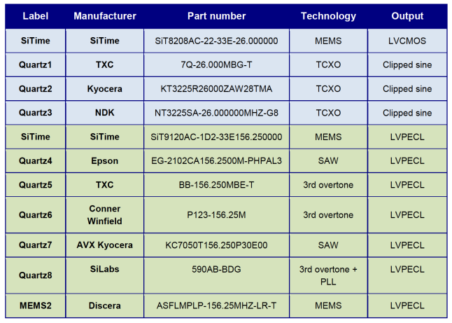
We performed EMS tests on a variety of commercially available quartz and MEMS-based oscillators operating at two different carrier frequencies (see Table 1).
Table 1. Oscillator devices under test; Single-ended parts (shaded blue) operate at 26 MHz and differential parts (shaded green) operate at 156.25 MHz
3 Experimental Results
Data on average noise spurs show that the SiTime differential MEMS oscillator outperforms competing differential MEMS and quartz based oscillators by up to 35 dB, equivalent to 54 times greater immunity to a radiated field as shown in Figure 5. The SiTime single-ended oscillator outperforms its quartz-based counterparts by up to 12 dB, or 4 times more immunity to a radiated field as shown in Figure 6. This is because the amplitude of the primary noise spurs is lower for SiTime MEMS oscillators than for quartz oscillators. The average spur power, calculated as the root of the sum of the squares according to Equation 2, is therefore much lower.
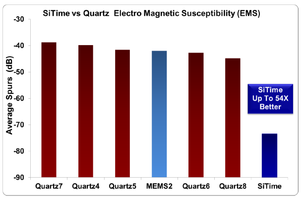
Figure 5: Susceptibility of differential oscillators to radiated electromagnetic field, 80 MHz-1 GHz
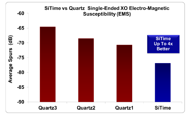
Figure 6: Susceptibility of single-ended oscillators to radiated electromagnetic field, 80 MHz-1 GHz
4 Oscillators Design to Reduce EMI Sensitivity
The results are not consistent with the idea that the metal can enclosures surrounding quartz oscillators provide improved protection from EMI as compared to plastic packaging. SiTime MEMS oscillators are packaged in plastic, yet they exhibit a lower degree of EMI-induced noise spurs. Something besides packaging must explain the variation in EMS between MEMS-based and quartz-based oscillators. The answer may lie in either the resonator or its accompanying oscillator circuitry, both of which can be sensitive to EMI.
Quartz crystals are piezoelectric materials and accumulate electrical charge in response to mechanical vibration. Their operating frequency can therefore be affected by incoming electrical signals such as unwanted EMI, negatively impacting the reliability of the clock signal. SiTime's silicon MEMS resonators exhibit mechanical vibration via electrostatic excitation and are therefore naturally less sensitive to incoming EMI. They are precisely tuned, with high Q values that reject external noise.
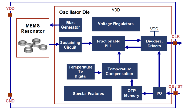
Figure 7: SiTime MEMS oscillator architecture
The driving circuitry behind SiTime MEMS oscillators is an analog circuit (shown in Figure 7) that optimizes performance in electrically noisy conditions, including those with high levels of EMI. The oscillator design includes differential circuits that inherently reject any coupled common mode noise. Other quartz and MEMS oscillator designs rely more on packaging and not noise suppressing analog circuits, and hence do not have this advantage.
5 Conclusions
SiTime MEMS oscillators are especially resilient to jitter-inducing external sources of EMI. This is true even for high frequency EMI noise in ranges where competitors’ oscillators experience significant signal degradation. As per the results shown by SiTime commissioned tests performed at an accredited third-party lab and other studies on EMI [1] [2], piezoelectric quartz devices are more susceptible to EMI. SiTime oscillators are therefore an excellent choice for reliable operation in potentially noisy, unpredictable environments where large electromagnetic sources may be present.
6 References
[1] “Electromagnetic Interference and Start-up Dynamics in High Frequency Crystal Oscillator Circuits”, Ulrich L. Rohde, Ajay K. Poddar, Frequency Control Symposium (FCS), 2010 IEEE International.
[2] "Test Method Standard, Microcircuits" MIL-STD-883H, U.S. Defense Logistics Agency, 2010.
[3] “EMI-Induced Failures in Crystal Oscillators”, J.-Jacques Laurin, S. G. Zaky, K. G. Balmain, IEEE Trans. on Electromagnetic Compatibility, Vol. 33, No. 4, pp. 334-342, Nov. 1991.
[4] "NEBS Requirements: Physical Protection", GR-63, Telcordia, 2012.
[5] “IEC 61000-4-3 ed3.2: Electromagnetic compatibility (EMC) - Part 4-3: Testing and measurement techniques - Radiated, radio-frequency, electromagnetic field immunity test”, IEC, March 2010.